GE HEALTHCARE
DIRECTION 5394141, REVISION 5 LOGIQ™ P5 SEVICE MANUAL
10-18 Section 10-6 - Electrical Safety Tests
10-6-5-3 Dale 600 Meter Procedure
When measuring system chassis currents with the Dale 600, always use the CHASSIS selection of the
external/chassis function switch. This requires the ground clip lead and changing the meters switches
in accordance with the IEC 601-1.1. refer to the Dale 600 Instruction Manual for meter self-test and
operation. Record the highest leakage current measured.
Follow these steps to test the unit for leakage current.
1.) Turn the LOGIQ™ P5 unit OFF.
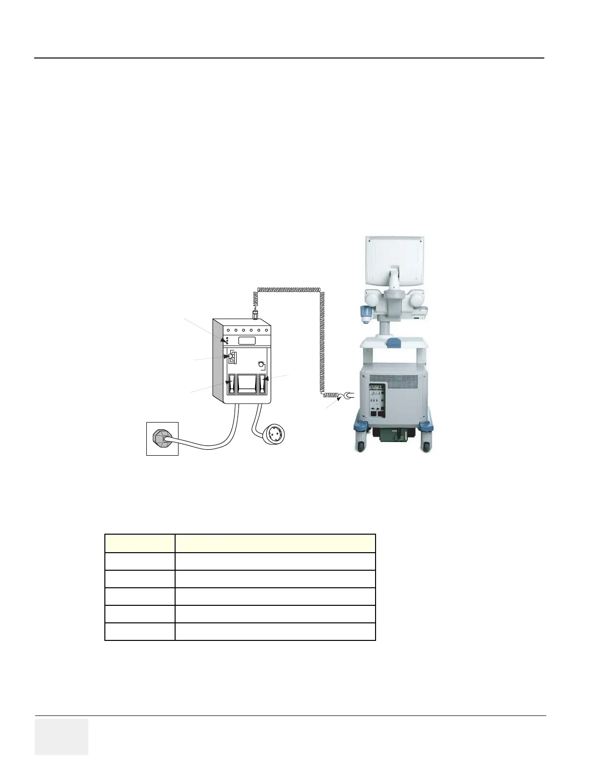
2.) Plug the unit into the meter, and the meter into the tested AC wall outlet
3.) Plug the black chassis cable into the meter's “CHASSIS” connector and attach the black chassis
cable clamp to an exposed metal part of the LOGIQ™ P5.
4.) Set the tester's “FUNCTION” switch to CHASSIS position.
5.) Follow the test conditions described for respective test points shown in Table 10-17.
6.) Keep a record of the results with other hard copies of PM data kept on site.
Figure 10-6 Ground and Chassis Leakage Current Test
Table 10-17 Chassis Leakage Current Test Condition
TEST CONDITION
1
Mounting screw for probe receptacle
2
caster support
3
Mounting screw for CRT housing
4
Mounting screw for peripheral plugged into unit
5
Mounting screw for other peripheral powered by unit
Chassis
Cable
Clamp
Normal
Reverse
Polarity
Neutral
Open/Closed
Functions
Selector
Outlet Test
Lamps

 Loading...


