Connection
Inputs and outputs, remote controls
MGCplus A0534-30.0 HBM: public 91
I/OFunctionPin
7 Not assigned
8 Ground
9 SDA for XM001 external memory module Input
10 SLC for XM001 external memory module Output
11 Transducer supply voltage 5V (max. 300mA)
1)
Output
12 F1+ rotational speed 0, angle of rotation, torque, frequency Input
13 F1- rotational speed 0, angle of rotation, torque, frequency Input
14 F2- rotational speed 90, calibration signal trigger Input/output
15 F2+ rotational speed 90, calibration signal trigger ground Input/output
1)
The current information is for the maximum permitted continuous currents of the AP17. The
number of connection boards per housing is not limited, but a maximum of three connection
boards can be used for transducer supply (5V/16V, for example for torque flange
T10F-SF1).
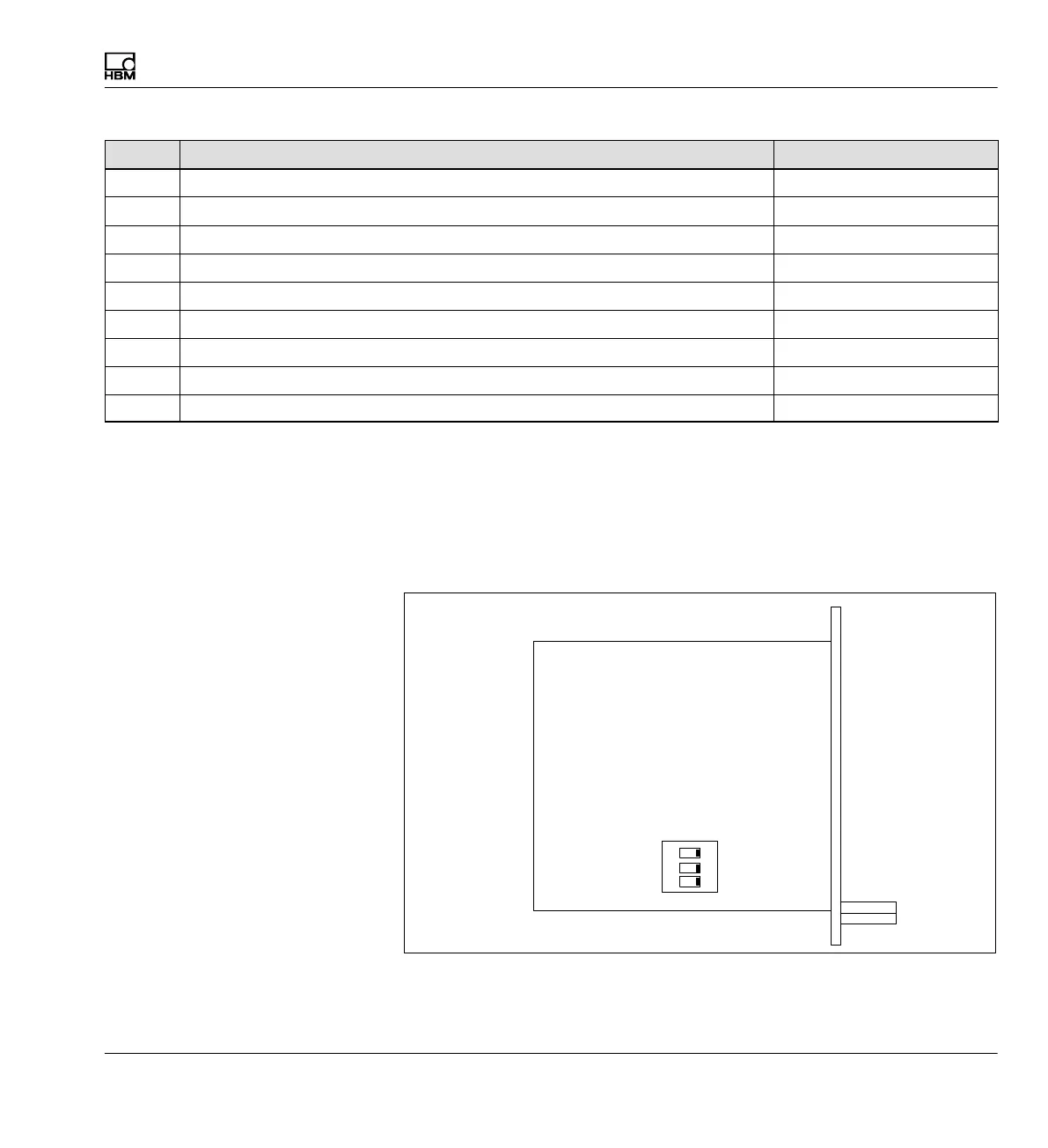
Termination resistors must be connected for long lines (>100m) and high
frequencies (>200kHz). To do this the 3x DIP switch S2 on the motherboard
of the AP17 must be switched to "ON".
1
2
3
ON
Switch S2
AP17
Fig. 4.6 AP17 component layout