D1 Servo Drive User Manual Servo Drive Configuration
HIWIN MIKROSYSTEM CORP. 5-67
(2) Pulse type selection
D1 servo drive supports three pulse types. For more information, please refer to section 3.1.1.
For pulse type selection, please refer to below.
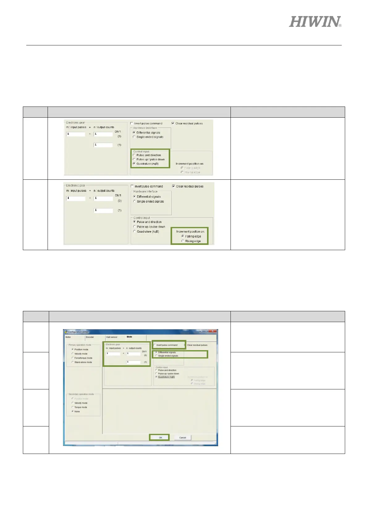
Table5.8.1.2
In the setting page of Mode, select
pulse type in the setting area of
Control input.
In the setting page of Mode, select
trigger method in the setting area of
Increment position on.
Note: This setting is required only when
Pulse and direction or Pulse up/pulse
down is selected.
(1) Electronic gear ratio setting
D1 servo drive supports two electronic gear ratios. For more information, please refer to section
5.4.1. For setting electronic gear ratio, please refer to below.
Table5.8.1.3
In the setting page of Mode, user can
set electronic gear ratio in the setting
area of Electronic gear which is
indicated by (a) in the left figure.
In the setting page of Mode, user can
set to invert pulse command in the
setting area of Invert pulse command
which is indicated by (b) in the left
figure.
In the setting page of Mode, select
Differential signals or Single ended
signals based on the wiring in the
setting area of Hardware interface. It
is indicated by (c) in the left figure.
After settings, click on OK button which
is indicated by (d) in the left figure.