D1 Servo Drive User Manual Servo Drive Configuration
HIWIN MIKROSYSTEM CORP. 5-41
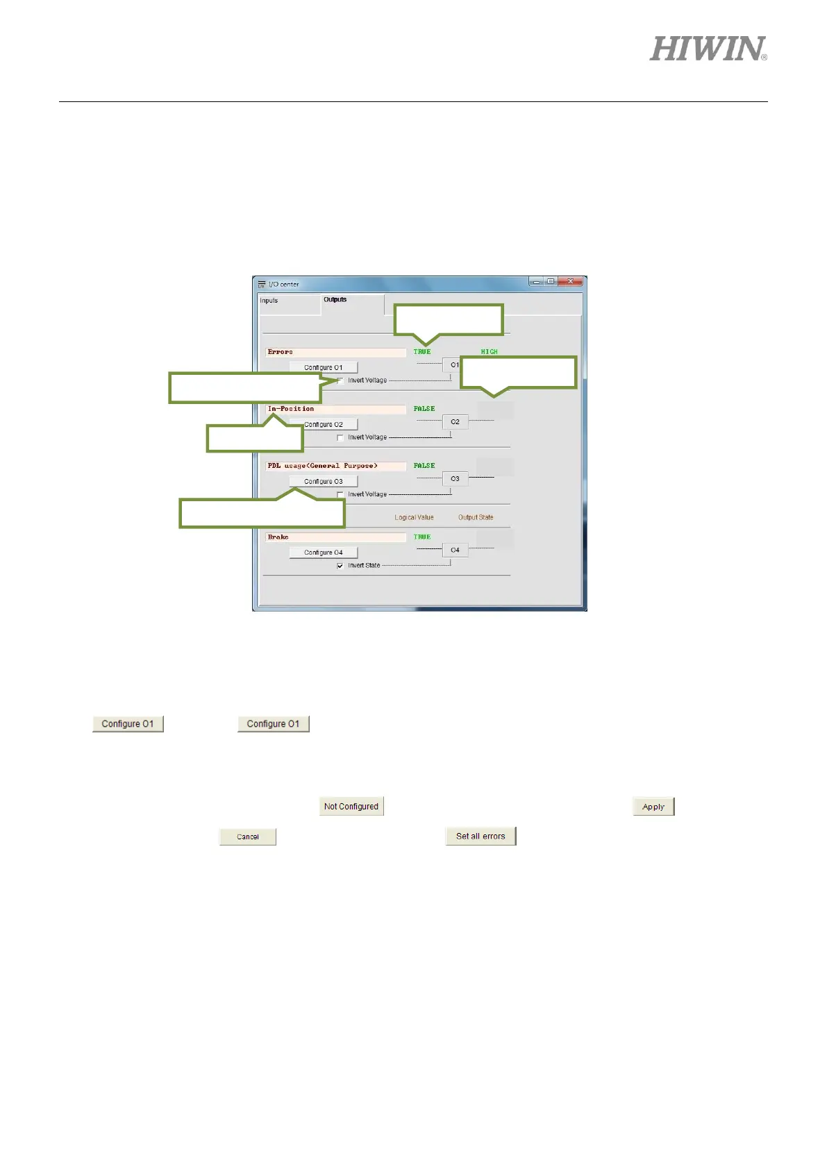
5.4.2 Digital outputs
D1 servo drive provides four sets of programmable digital outputs. Three outputs (O1 to O3) are
general-purpose outputs which locate on connector CN2. One output (O4) which locates on the connector
for 24 V power supply is for brake and can also be used as general-purpose output.
Figure5.4.2.1
(1) Output function setting
Each output has its corresponding setting button. For instance, the setting button of O1 is
. Click on to show the setting window as figure 5.4.2.2. Output functions in
figure 5.4.2.2 can be categorized into Statuses, Errors and Warnings. If two or more output
functions are selected for one output, the output will be ON as either one of the selected output
functions is triggered. Click on to cancel the selection. Click on to finish the
setting or click on to cancel the setting. If is clicked on, all the listed errors will
be selected. For safety, it is suggested to select all the listed errors.
(2) Status field
When a function is set for an output, the name of that function will be displayed in the status field. If
two or more functions are set for one output, the status field will display “Customized”. If all the listed
errors are selected, the status field will display “Errors” as figure 5.4.2.1. If no function is set, the
status field will display “PDL usage (General purpose)”.