D1 Servo Drive User Manual Servo Drive Configuration
HIWIN MIKROSYSTEM CORP. 5-19
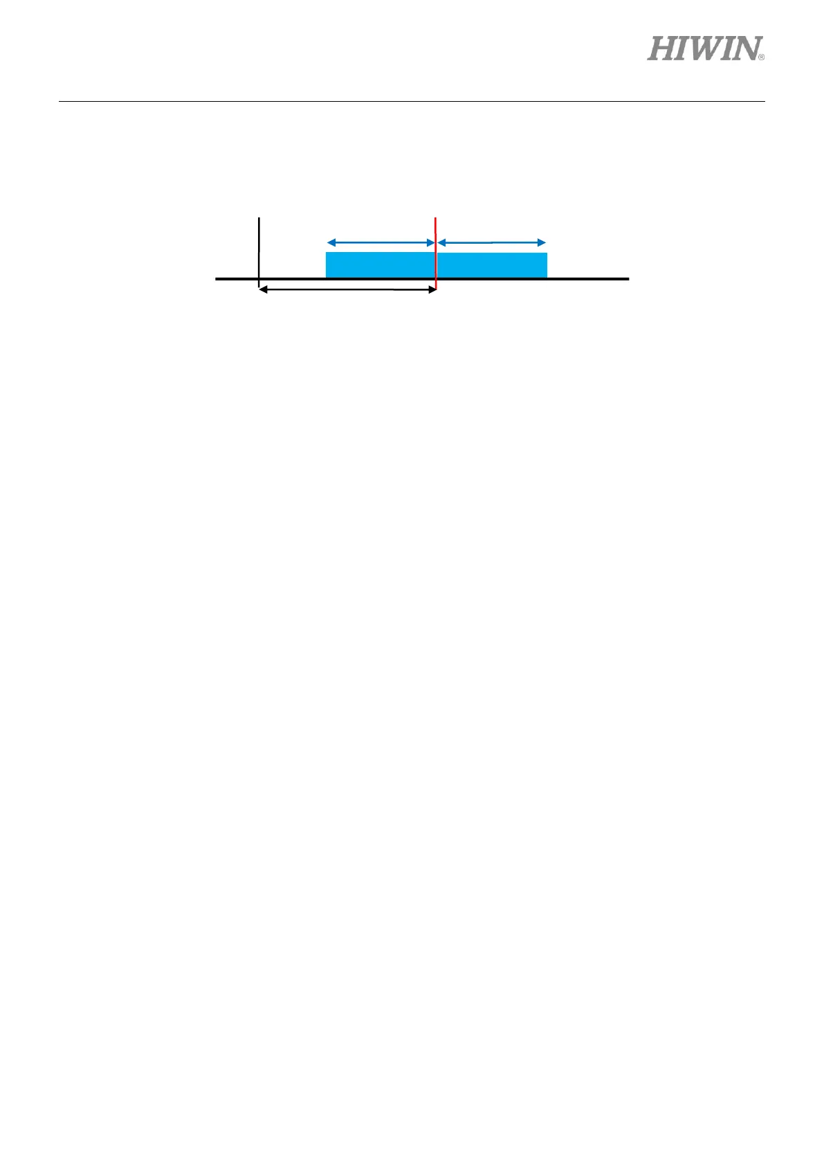
When home offset is used in homing, the emulated Z-phase signal will move to the home position
after home offset, as figure 5.2.2.3.6.
Figure5.2.2.3.6
(4) Emulated Z-phase signal output in every revolution
This function can only be used with direct drive motor.
➢ When Emulated Index Output in every revolution is not selected
The servo drive outputs Z-phase signal when the index position is reached in the first
revolution.
➢ When Emulated Index Output in every revolution is selected
The servo drive outputs Z-phase signal every time when the index position is reached.
Note:
(1) For firmware version before D1 MDP 0.247 and D1COE MDP 0.327, if emulated encoder output
function is enabled when digital encoder is used, emulated Z-phase signal will be output when the
index position is reached in the first revolution. The signal width will be twice the set emulated index
radius. For firmware version after D1 MDP 0.247 and D1COE MDP 0.327, emulated Z-phase signal
is output every time when the index position is reached. The signal width is the set emulated index
radius.
(2) For linear motor, multiple index signal output only supports digital encoder.
5.2.3 Setting Hall sensor
Since D1 servo drive is able to complete phase initialization without Hall sensor, None is selected in the
setting page shown in figure 5.2.3.1. Only when Hall sensor is used, the setting of Hall sensor is required.
D1 servo drive supports both digital Hall sensor and analog Hall sensor. The setting of Hall sensor must
be based on the actual application. If Digital hall sensor or Analog hall sensor is selected when no Hall
sensor is used, it may cause abnormal operation of the servo drive or motor. If analog Hall sensor is used,
the servo drive will regard it as encoder, so user does not need to install another encoder.
Coordinates of servo drive = 0