EasyManua.ls Logo

Hiwin D1 - Basic Specifications

Hiwin D1
307 pages
Print Icon
To Next Page IconTo Next Page
To Previous Page IconTo Previous Page
Loading...
Specifications D1 Servo Drive User Manual
2-4 HIWIN MIKROSYSTEM CORP.
MD20UE01-2109
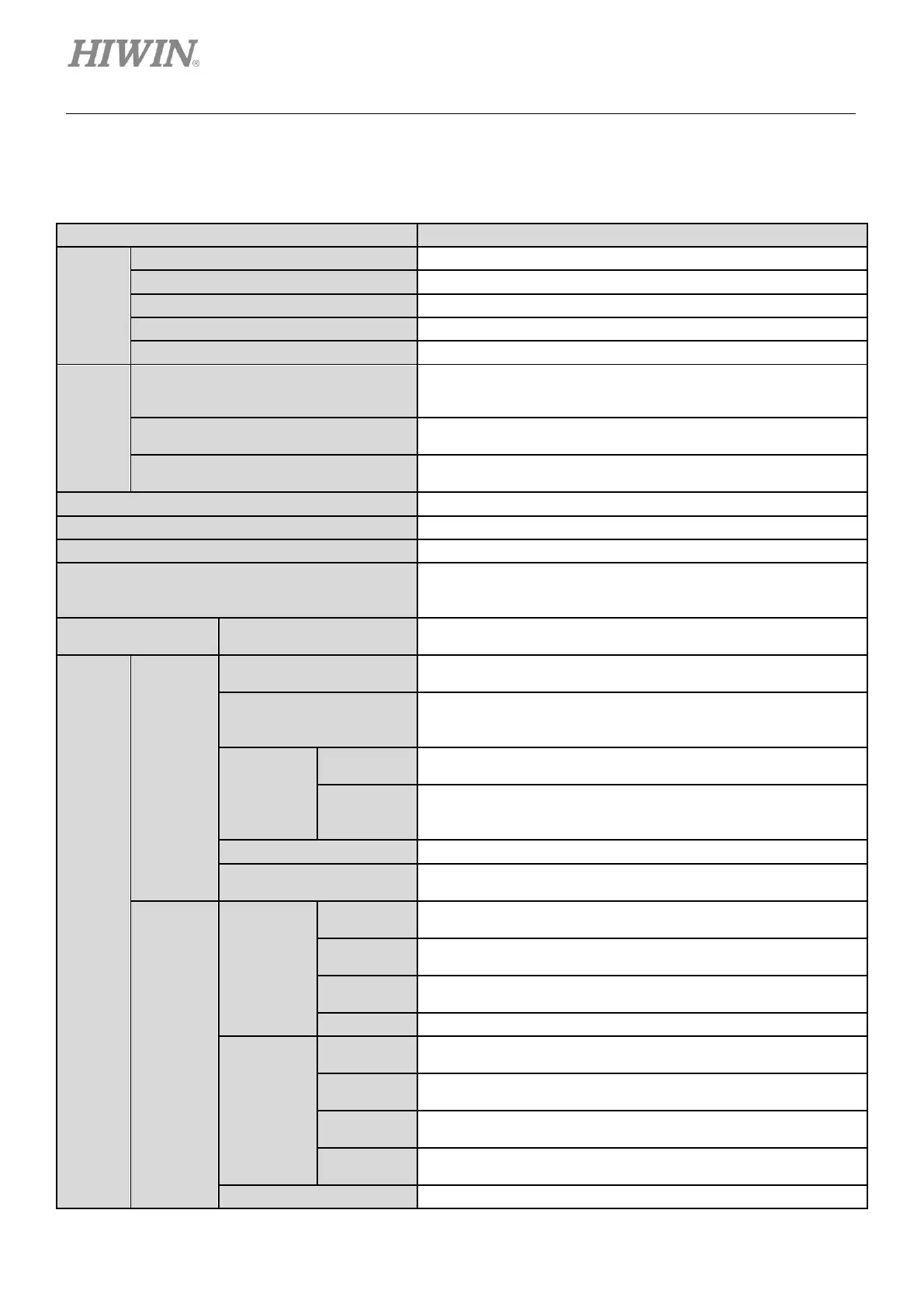
2.2 Basic specifications
Table2.2.1
D1
D1-36
Input
Power
Voltage
100 - 240 Vac ±10%
Frequency
47 to 63 Hz
Phase
1 Ø or 3 Ø
Control Voltage
+24 Vdc ±10%
Control Current
1 A minimum
Output
Power
Continuous Current
12 A_amp
[8.5 A_rms]
(Note: with external heat sink)
Instantaneous Current
36 A_amp
[25.4 A_rms]
Allowable Continuous Time for
Instantaneous Current
1 second maximum
Servo Drive Startup Time
1~2 seconds
Servo Drive Reset Time
3~4 seconds
Main Circuit Control
IGBT PWM space vector control
Control Motor Type
13 bit AC servo motor
Linear motor
Torque motor
Status LED Indicator
Servo Drive Status
Red: Error
Green: Servo ready
Control
Mode
Position
Mode
Input Pin
[I9, I9M], [I10, I10M] differential inputs or I9, I10 single-ended
inputs
Pulse Command Type
Pulse/Direction
CW/CCW
AqB
The
Maximum
Input Pulse
Frequency
Differential
Signal
Pulse input (2 M pulses/s max.); Quad A/B (8 M counts/s max.)
Single-
ended
Signal
Pulse input (500 K pulses/s max.); Quad A/B (2 M counts/s
max.)
Command Source
Pulse from controller
Electronic Gear
Electronic gear ratio: pulses /counts
Pulses: 1~2147483647; Counts: 1~2147483647
Velocity
Mode
Analog
Input
Command
Input
Impedance
10
Voltage
Range
±10 Vdc
Time
Constant
2.2 us
Resolution
12 bits
Digital Input
Command
PWM 100%
I9: PWM = 0% - 100%
I10: Direction = 1/0
PWM 50%
I9: PWM = 50% ± 50%
I10: No function
Frequency
Range
36.5 KHz minimum, 100 KHz maximum
Pulse Width
Limit
220 ns minimum
Command Source
Voltage or PWM from controller

Table of Contents

Related product manuals