D1 Servo Drive User Manual Tuning
HIWIN MIKROSYSTEM CORP. 6-21
If the desired performance cannot be achieved by simply adjusting common gain, D1 servo drive also
provides advanced gains for advanced tuning, including filter, acceleration feedforward (Acc
feedforward), schedule gains and velocity loop gain (Schedule Gains + vpg), analog input correction and
current loop.
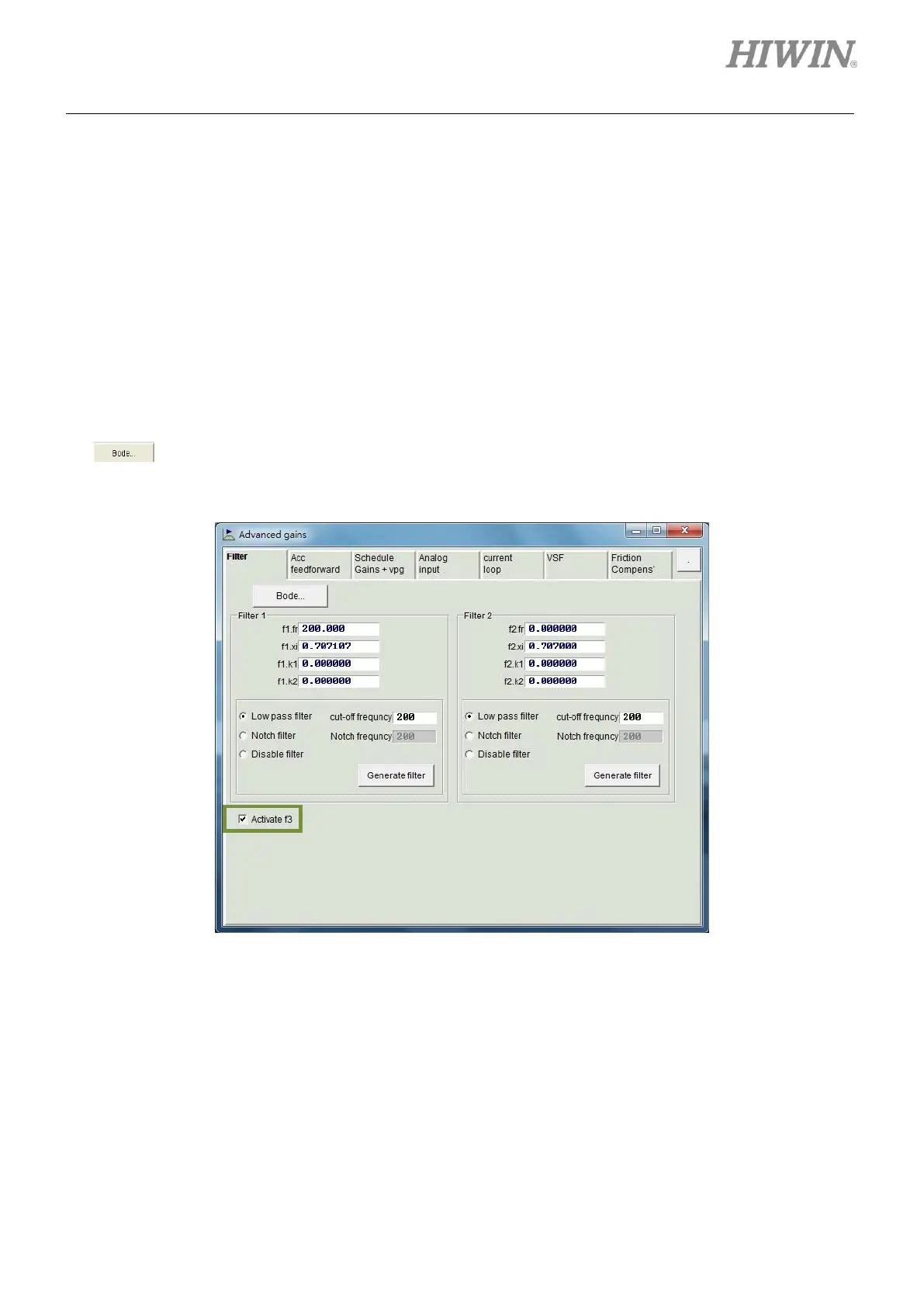
6.6.1 Filter
Two filters are provided in the servo drive. They can be set as low-pass filters or notch filters to eliminate
high-frequency vibration and deal with resonance frequency to enhance controlling performance.
Frequency analyzer is commonly used to analyze system characteristics while configuring a filter. Click
on in figure 6.6.1.1 to open simulation interface for Bode plot. The settings for low-pass filter and
notch filter will be described as below.
Figure6.6.1.1 Filter
(1) Low-pass filter
① fr: fr is the cutoff frequency (Unit: Hz). For normal application, user can set cutoff frequency to
500 Hz. For other application, user can consider decreasing the value of cutoff frequency. If the
cutoff frequency is set to be too low, it may affect the controlling performance.
② xi: Damping ratio (Setting range: 0 to 1)
③ k1: 0
④ k2: 0