D1 Servo Drive User Manual Wiring
HIWIN MIKROSYSTEM CORP. 4-23
4.7.6 Wiring diagram for PWM command input
In velocity mode and force/torque mode, in addition to analog command, D1 servo drive can also receive
PWM command. Two PWM command types are supported, PWM 50% and PWM 100%. For more
information, please refer to section 5.2.4.
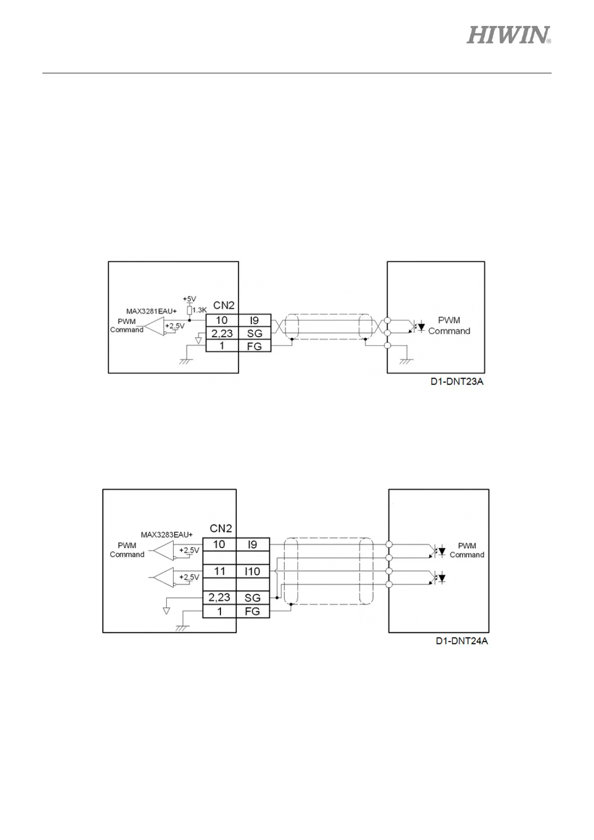
(1) Wiring example for PWM 50%
While using PWM 50%, I9 is used to receive PWM command and I10 has no function. Refer to the
wiring below.
Figure4.7.6.1
(2) Wiring example for PWM 100%
While using PWM 100%, I9 is used to receive PWM command and I10 is used to receive direction
command. Refer to the wiring below.
Figure4.7.6.2
mega-fabs
D1 series servo drive
mega-fabs
D1 series servo drive