Specifications D1 Servo Drive User Manual
2-10 HIWIN MIKROSYSTEM CORP.
2.4 Installation
If the servo drive is installed in a control box, ensure it is mounted with conductive screws. The insulating
materials, such as paint, on the contact surface of the control box must be removed for grounding the
servo drive through the control box. When the input power of the servo drive is 220 V, the grounding
resistance must be lower than 50 Ω; when the input power of the servo drive is 110 V, the grounding
resistance must be lower than 100 Ω.
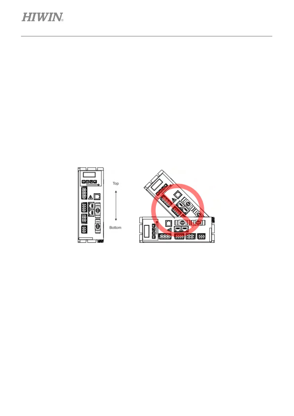
The suction hole and vent hole of the servo drive must not be obstructed. Install the servo drive according
to the specified orientation; otherwise, it may malfunction. For well cooling and circulation effect, there
must be enough clearance between the servo drive and the adjacent objects or baffle plates. While
installing multiple servo drives, the clearance between two servo drives must be at least 20 mm. Install a
fan in the control box to facilitate heat dissipation.
Figure2.4.1