D1 Servo Drive User Manual Operation Principles
HIWIN MIKROSYSTEM CORP. 3-5
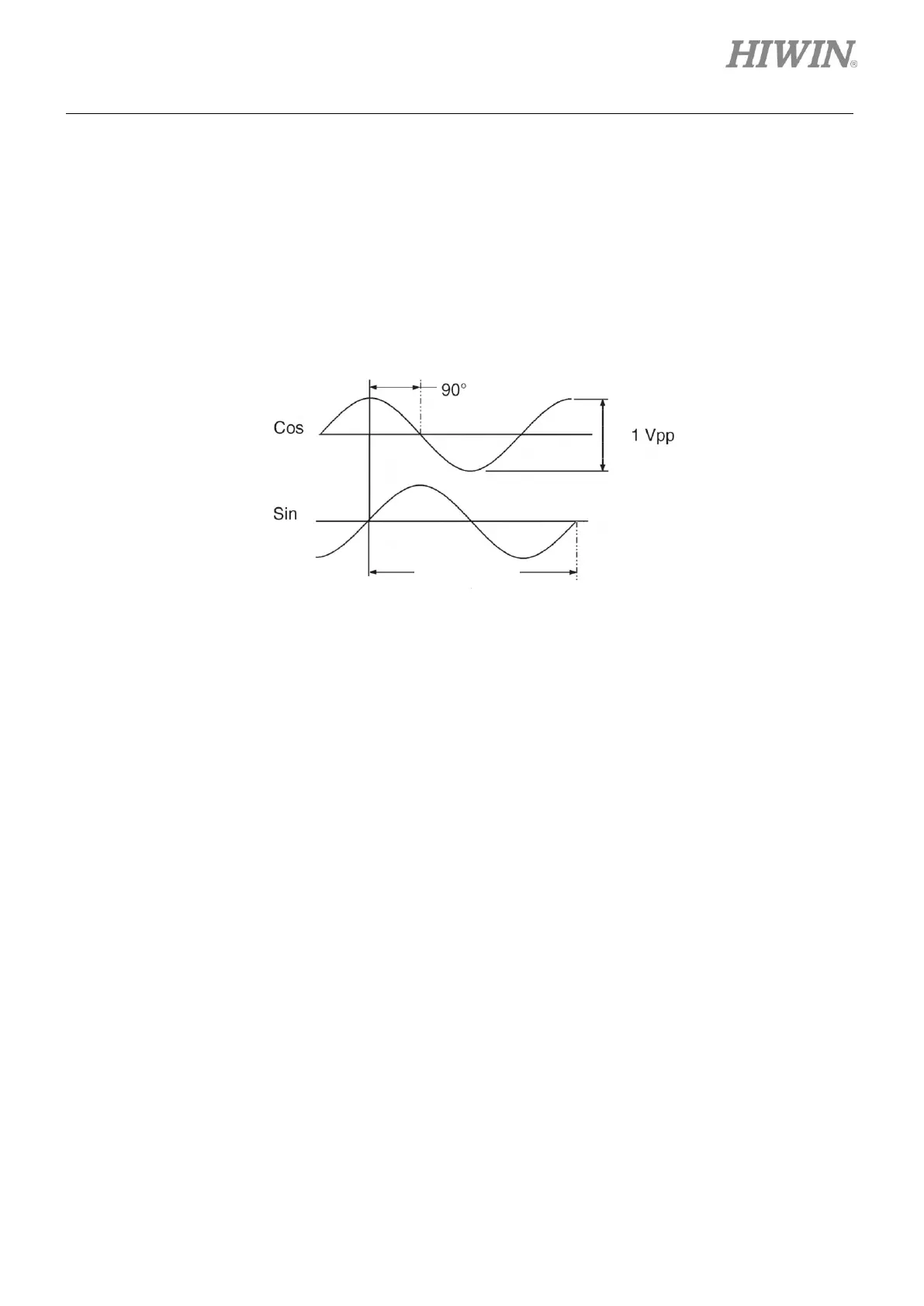
3.2.2 Analog type
Analog encoder outputs signal with two phases, sin and cos. The output signal is usually 1 Vpp
differential signal. 1 Vpp differential signal consists of two sinusoidal signals with 90 degrees phase
difference. The specification of analog encoder is usually shown by grating period. For instance, the
grating period of commonly-used linear analog optical scale is 40 um. The grating period can be finer by
adjusting multiplier factor in D1 servo drive to have better resolution than nanometer.
Figure3.2.2.1
3.3 Buffered encoder output and emulated encoder output
The input signal from encoder is used by the servo drive to perform servo control. When the servo drive is
used with controller, the servo drive transmits the position or angle signal received from encoder to the
controller. D1 servo drive provides two types of encoder signal outputs.
(1) Buffered encoder output
When buffered encoder output is selected, signals received from encoder are directly sent to
controller. Invert function is provided in D1 servo drive. When invert function is selected, the signals
received from encoder will be inverted before being sent to controller.
(2) Emulated encoder output
When emulated encoder output is selected, the position information received from encoder will be
multiplied by a scale factor before being sent to controller. In some occasions, if controller cannot
receive encoder signals sent at high frequency, a scale factor can be set to lower the frequency. In
addition, if the multiplier factor of an analog encoder is set to be too high, a scale factor can also be
set to lower the resolution of encoder output. When motor reaches home position for the first time,
the width of output Z-phase signal is half of its original width.