D1 Servo Drive User Manual Wiring
HIWIN MIKROSYSTEM CORP. 4-15
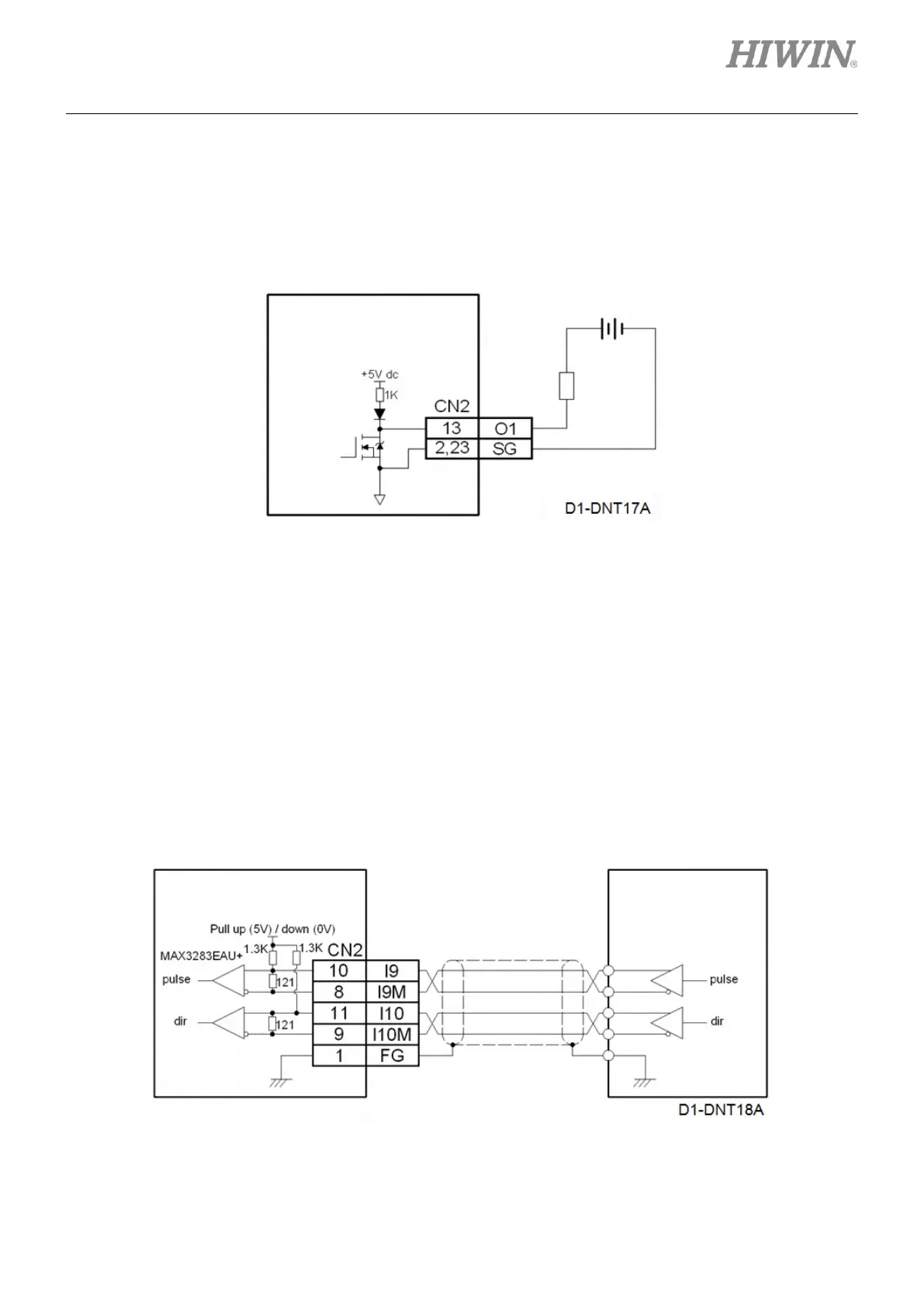
(3) Wiring example for directly connecting to external load
The output can be directly connected to load (For example, indicator). For the wiring method, please
refer to the figure below. The voltage and current of external DC power cannot exceed 40 V and 0.3
A.
Figure4.7.2.4
4.7.3 Wiring diagram for pulse command input
In position mode, I9, I9M, I10 and I10M are used to receive pulse command. There are two wiring
methods, please refer to below.
(1) Wiring example for controller sending differential signal
The setting of differential signal must be completed in Lightening, please refer to section 5.2.4. The
maximum input pulse frequency while using differential signal: pulse input (2M pulses/s max.) and
Quad A/B (8M counts/s max.).
Figure4.7.3.1
mega-fabs
D1 series servo drive
mega-fabs
D1 series servo drive