Wiring D1 Servo Drive User Manual
4-24 HIWIN MIKROSYSTEM CORP.
4.8 Wiring for feedback signals (CN3)
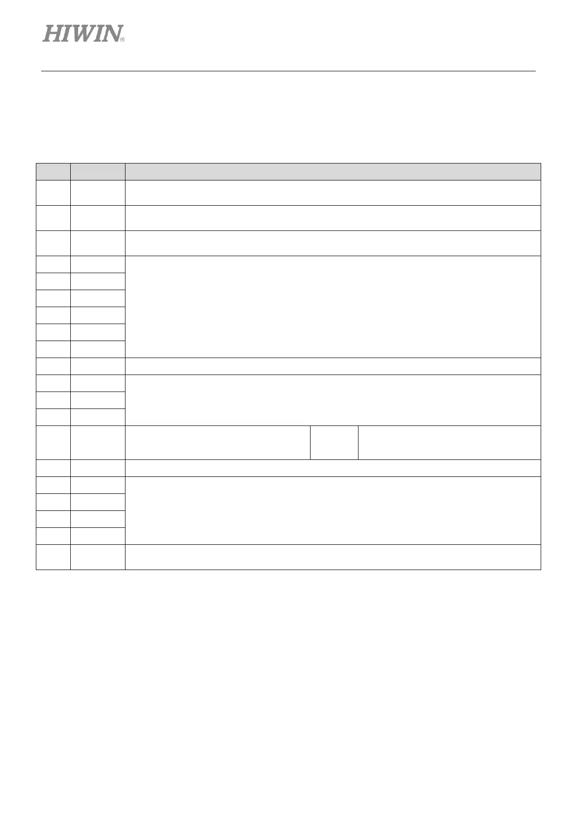
(1) D1--2 CN3 pin assignment
Table4.8.1
Frame ground
For connecting cable shield
Signal ground and +5 Vdc ground
If double-shielded cable is used, it is for connecting the inner shield.
Encoder and Hall sensor +5 Vdc power output
The total load current cannot exceed 400 mA.
Digital incremental encoder input
Signal ground and +5 Vdc ground
The default setting is for motor over
temperature switch, but it can still be set
for other function.
Set I5 as pull up or pull down in group B.
Signal ground and +5 Vdc ground
Analog incremental encoder input
Signal ground and +5 Vdc ground
If double-shielded cable is used, it is for connecting the inner shield.