D1 Servo Drive User Manual Wiring
HIWIN MIKROSYSTEM CORP. 4-25
(2) D1--3 CN3 pin assignment
Table4.8.2
Frame ground
For connecting cable shield
Signal ground and +5 Vdc ground
If double-shielded cable is used, it is for connecting the inner shield.
Encoder and Hall sensor +5 Vdc power output
The total load current cannot exceed 400 mA.
Digital incremental encoder input
Signal ground and +5 Vdc ground
The default setting is for motor over
temperature switch, but it can still be set for
other function.
Pull up/pull down is group B.
Signal ground and +5 Vdc ground
Encoder error signal cable
Signal ground and +5 Vdc ground
If double-shielded cable is used, it is for connecting the inner shield.
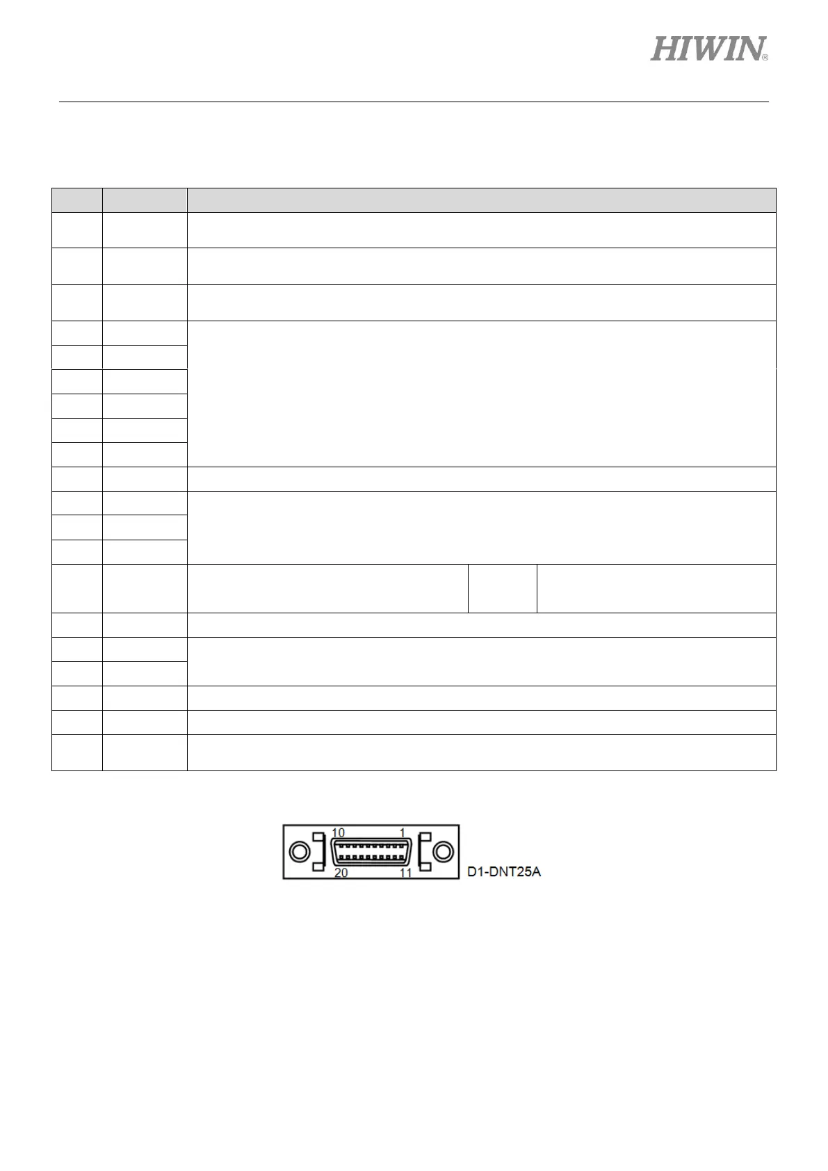
(3) Pin assignment of CN3
Figure4.8.1