D1 Servo Drive User Manual Wiring
HIWIN MIKROSYSTEM CORP. 4-9
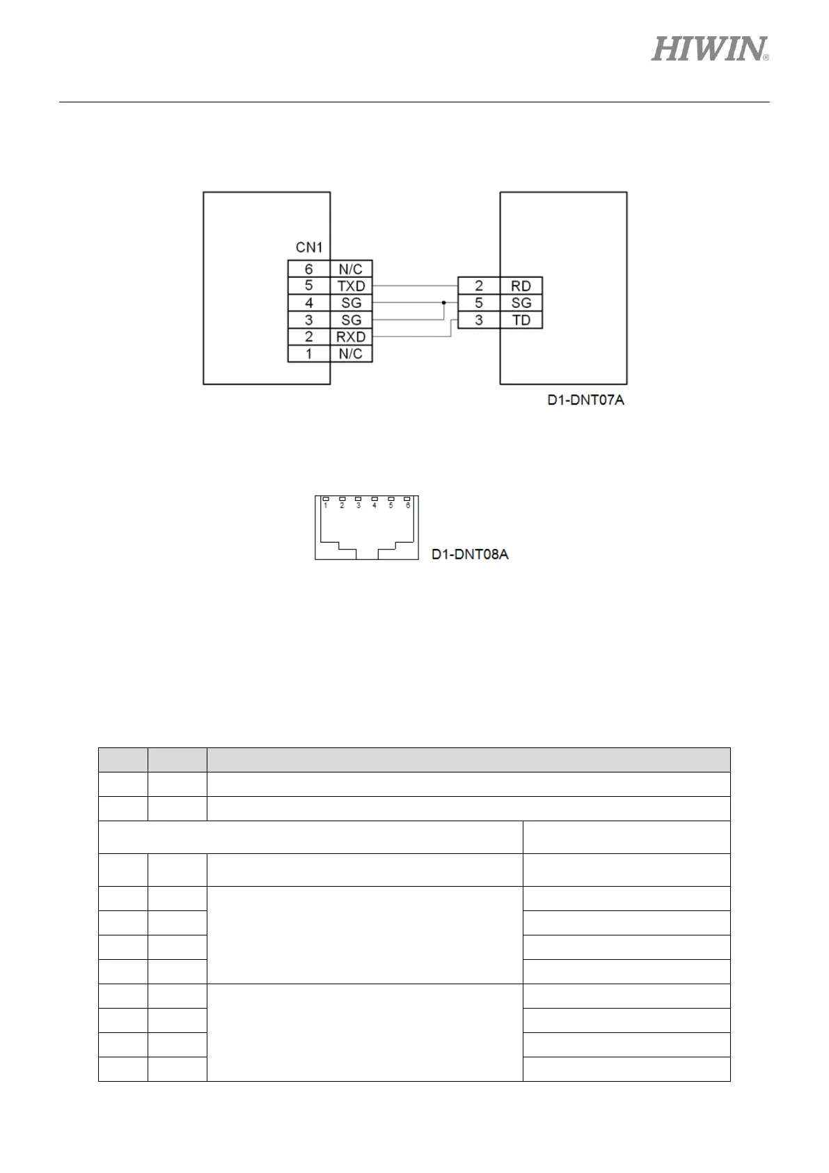
(2) Connection for RS232 communication
Use HIWIN LMACR21D RS232 communication cable.
Figure4.6.1
(3) CN1 RJ11 pin assignment
Figure4.6.2
4.7 Wiring for control signals (CN2)
(1) Pin assignment
Table4.7.1
Frame ground (For connecting cable shield)
Set inputs as pull up or pull
down in Lightening.
For enabling or disabling motor
The pin can also be set for other function.
General-purpose input signal (Programmable)
In position mode, these 4 pins are used for
receiving pulse command. In other mode, I9 and
I10 are general-purpose inputs. I9M and I10M
have no function. In velocity mode and
force/torque mode, I9 and I10 are for PWM
signal input.
mega-fabs
D1 series servo
drive