Wiring D1 Servo Drive User Manual
4-10 HIWIN MIKROSYSTEM CORP.
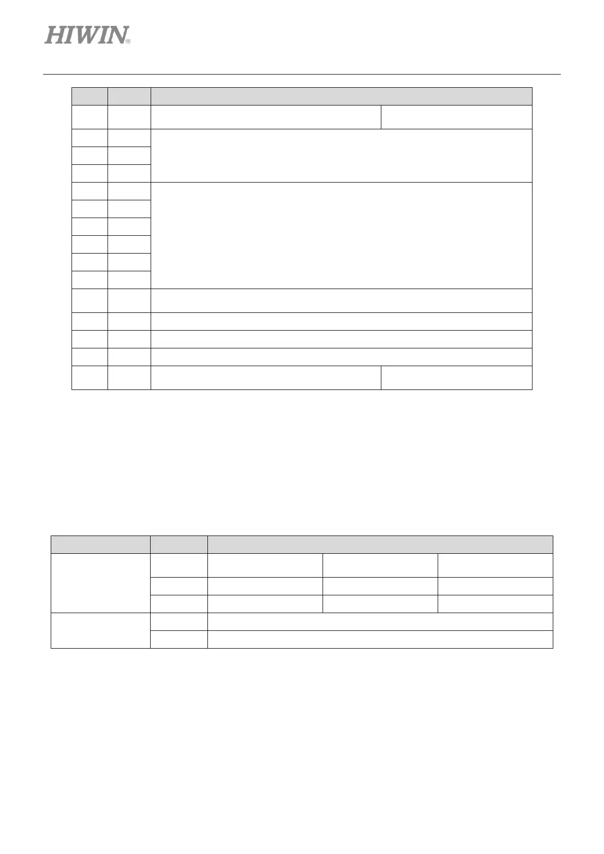
I11, general-purpose input signal
(Programmable)
General-purpose output signal (Programmable)
Feedback pulse output (Buffered encoder or emulated encoder)
Encoder +5 Vdc power output
The total load current cannot exceed 400 mA.
Positive pin for analog command input
Negative pin for analog command input
D1 model: I12, general-purpose input signal
(Programmable)
Note:
The high-level input voltage of pulse command and PWM command must be greater than 2 V. The low-level
input voltage must be lower than 0.8 V.
(2) Dedicated inputs in operation mode
The dedicated inputs in each operation mode are listed in the table below.
Table4.7.2
Pulse/Direction
command input
Force/torque mode
and velocity mode