D1 Servo Drive User Manual Wiring
HIWIN MIKROSYSTEM CORP. 4-11
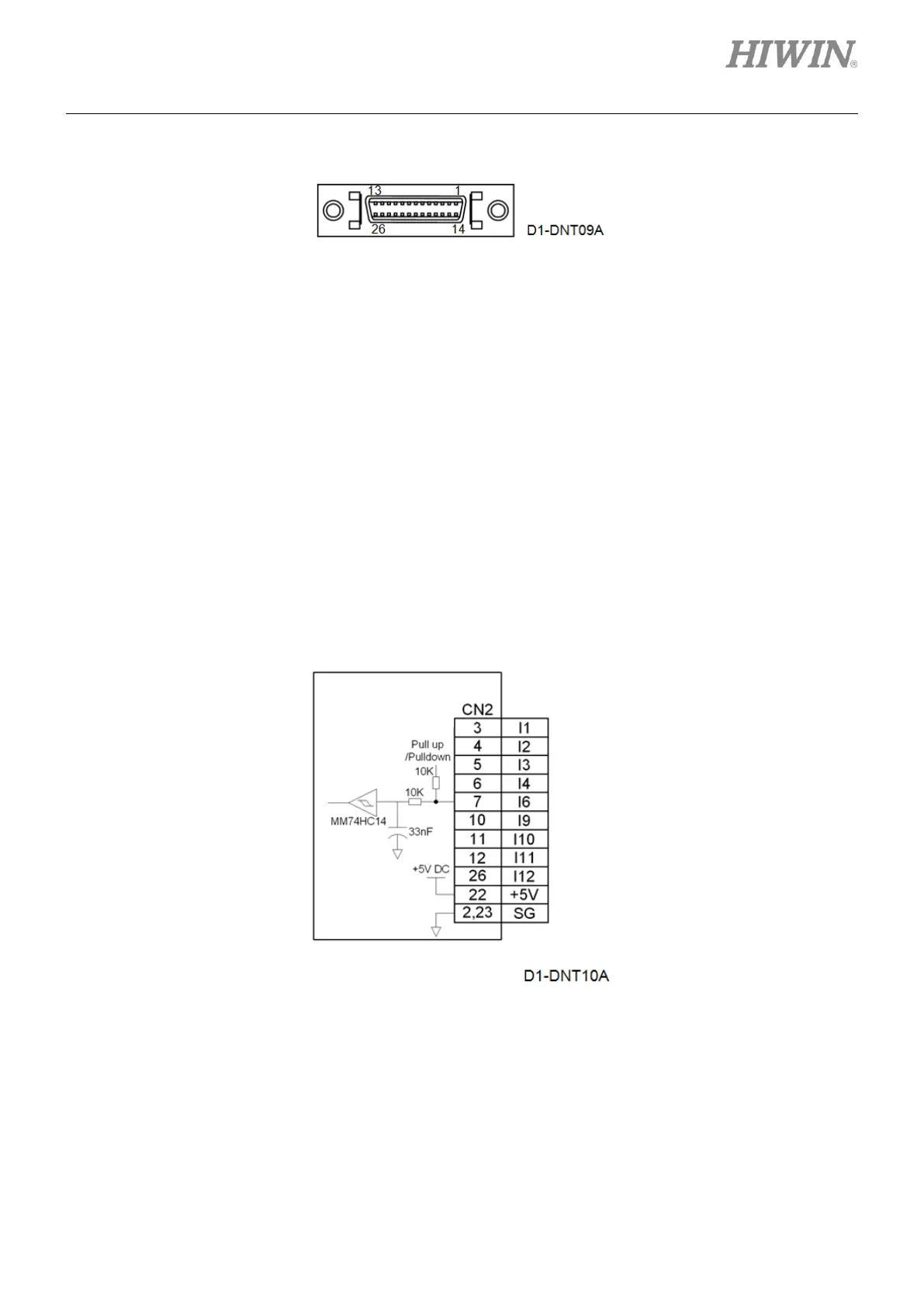
(3) CN2 pin assignment
Figure4.7.1
4.7.1 Wiring diagram for digital inputs
The CN2 connector on D1 servo drive provides 9 digital inputs. The input interface circuit is shown in the
figure below. The maximum voltages for I9 and I10 are 12 V, and the maximum voltages for other inputs
can be 24 V. The inputs of the servo drive can be set as pull up or pull down for different controller. When
the output of controller is sink type (For example, NPN transistor output), the input of the servo drive
should be set as pull up. When the output of controller is source type (For example, PNP transistor
output), the input of the servo drive should be set as pull down. To set the input as pull up or pull down in
Lightening, please refer to section 5.4.1.
Note:
The high-level input voltage must be greater than 2 V and the low-level input voltage must be lower than 0.8 V.
Figure4.7.1.1
The actual wiring may vary with the output type of controller. The wiring examples for controllers using
PNP transistor output, NPN transistor output and relay are provided below.
mega-fabs
D1 series servo
drive
The pull-up resistance (R) of I9 and I10 is
1.3 K. The pull-up resistance (R) of other
inputs is 10 K.