D1 Servo Drive User Manual Wiring
HIWIN MIKROSYSTEM CORP. 4-13
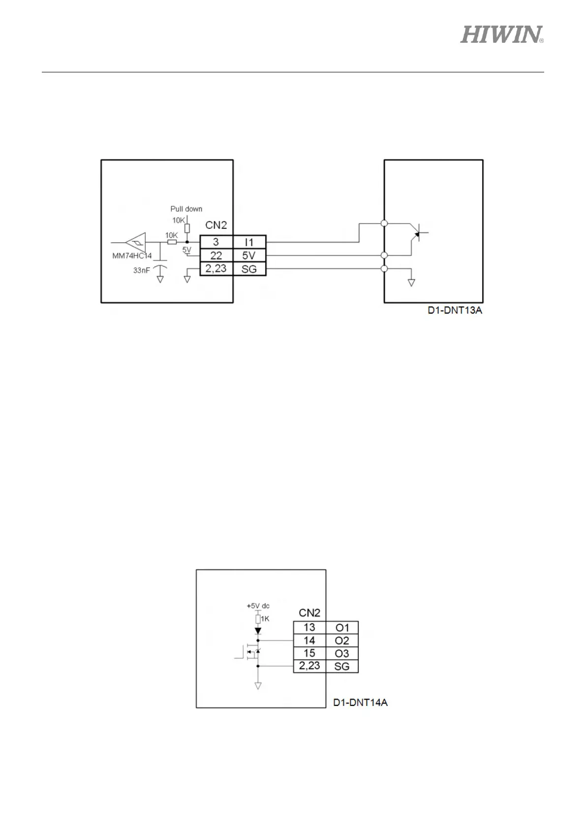
(2) The wiring example for general-purpose digital inputs (The output type of controller is source.)
The input group should be as pull down in Lightening.
a If the photoelectric switch in controller is using PNP transistor
Figure4.7.1.4
Note:
If the required power for the photoelectric switch in controller is 5 V, the 5 V power can be provided via pin 22
on CN2. The total load current must not exceed 400 mA.
4.7.2 Wiring diagram for digital outputs
The CN2 connector on D1 servo drive provides 3 digital outputs (O1~O3). The output interface circuit is
shown in the figure below. The outputs are open-drain outputs with allowable maximum voltage 40 V and
maximum current 0.3 A. Output O4 is on control power connector. O4 is usually used for brake output, but
it can also be set as general-purpose output. For setting output signal in Lightening, please refer to
section 5.4.2.
Figure4.7.2.1
mega-fabs
D1 series servo drive
mega-fabs
D1 series servo drive