Operation Principles D1 Servo Drive User Manual
3-14 HIWIN MIKROSYSTEM CORP.
3.8 Error compensation
Normally the positioning accuracy of a servo drive is decided by encoder. When an encoder cannot meet
user’s requirement for accuracy, user may use equipment with higher accuracy level (such as laser
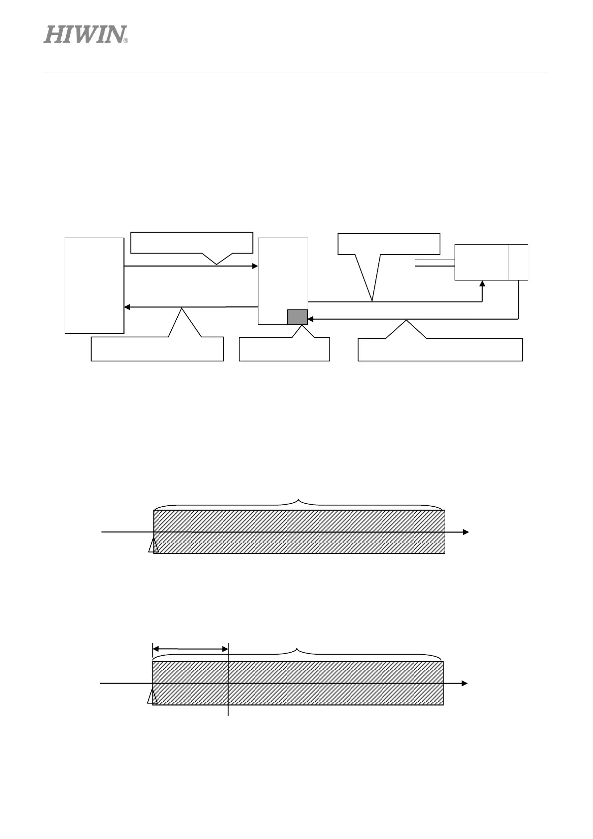
interferometer) to measure system error. As figure 3.8.1, D1 servo drive is able to store system error and
calculate error compensation value by means of linear interpolation between fixed distances to enhance
positioning accuracy.
Figure3.8.1
The effective range of error compensation is determined by index signal. Error compensation is effective
only in the positive direction starting from index signal. If home offset is applied, the effective range of
error compensation is still the same as home offset is set to zero.
Figure3.8.2
Encoder position feedback input
When home offset is set to 0
Servo drive coordinates = 0
Effective range of error compensation
When home offset is set to 100
Servo drive coordinates = 0
Effective range of error compensation
Servo drive
coordinates =
-100