Tuning D1 Servo Drive User Manual
6-48 HIWIN MIKROSYSTEM CORP.
6.9.1 Setting error map function
To use Error map function, please refer to the instructions below.
Step 1: Open Application center and select Error Map tab.
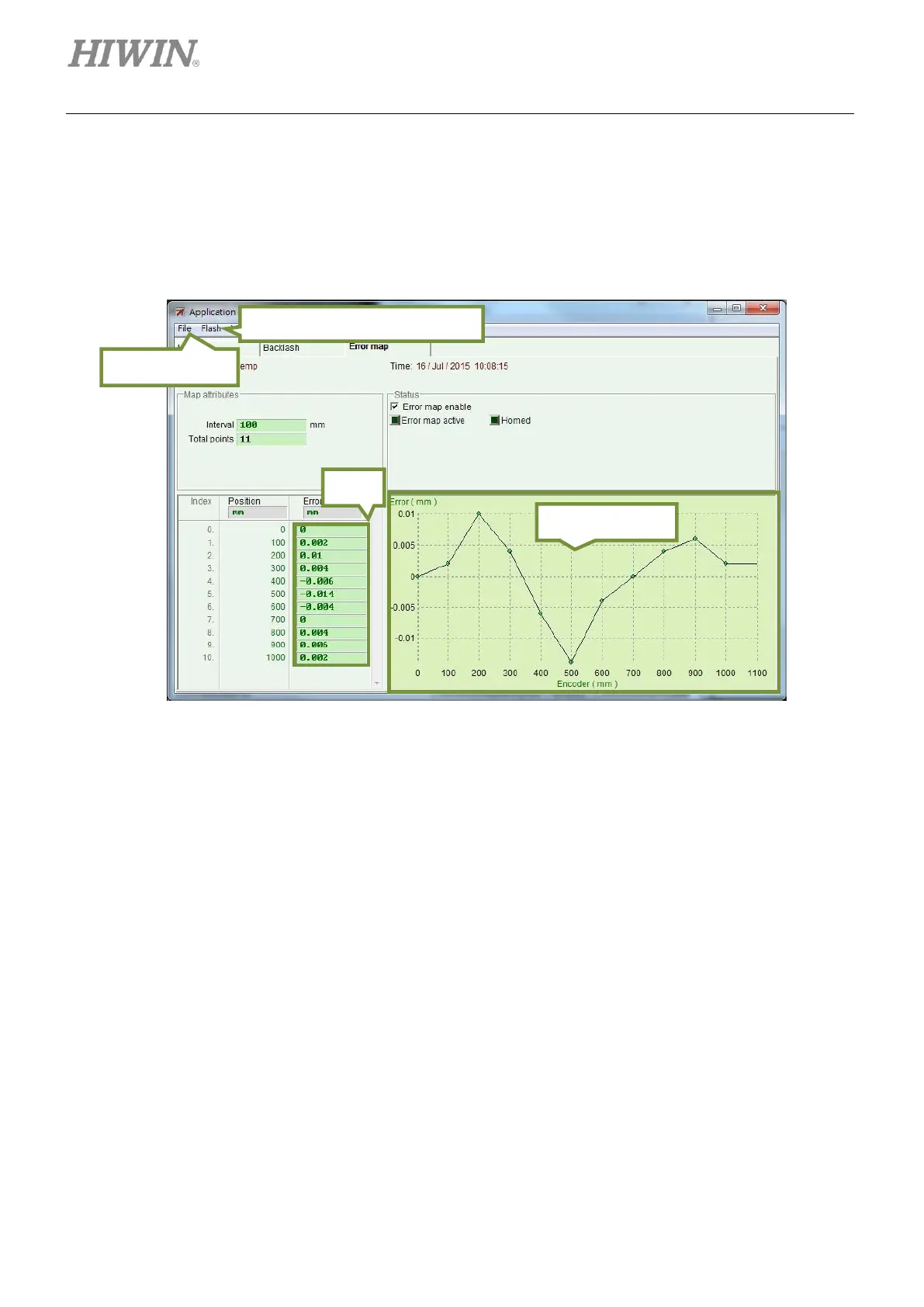
Figure6.9.1.1 Error map page
Step 2: Set Interval and Total points. Input the errors into the fields of Error. User is allowed to use
different units. In figure 6.9.1.1, the compensation range is from 0 to 1,000 mm. Interval is set
to 100 mm. Total points is set to 11. The errors in the fields of Error are obtained by laser
interferometer. Each value represents the positioning error at each target position. For
instance, for target position 100 mm, the actual position measured by laser interferometer is
100.002 mm.
Load from Flash/Save to Flash