Wiring D1 Servo Drive User Manual
4-8 HIWIN MIKROSYSTEM CORP.
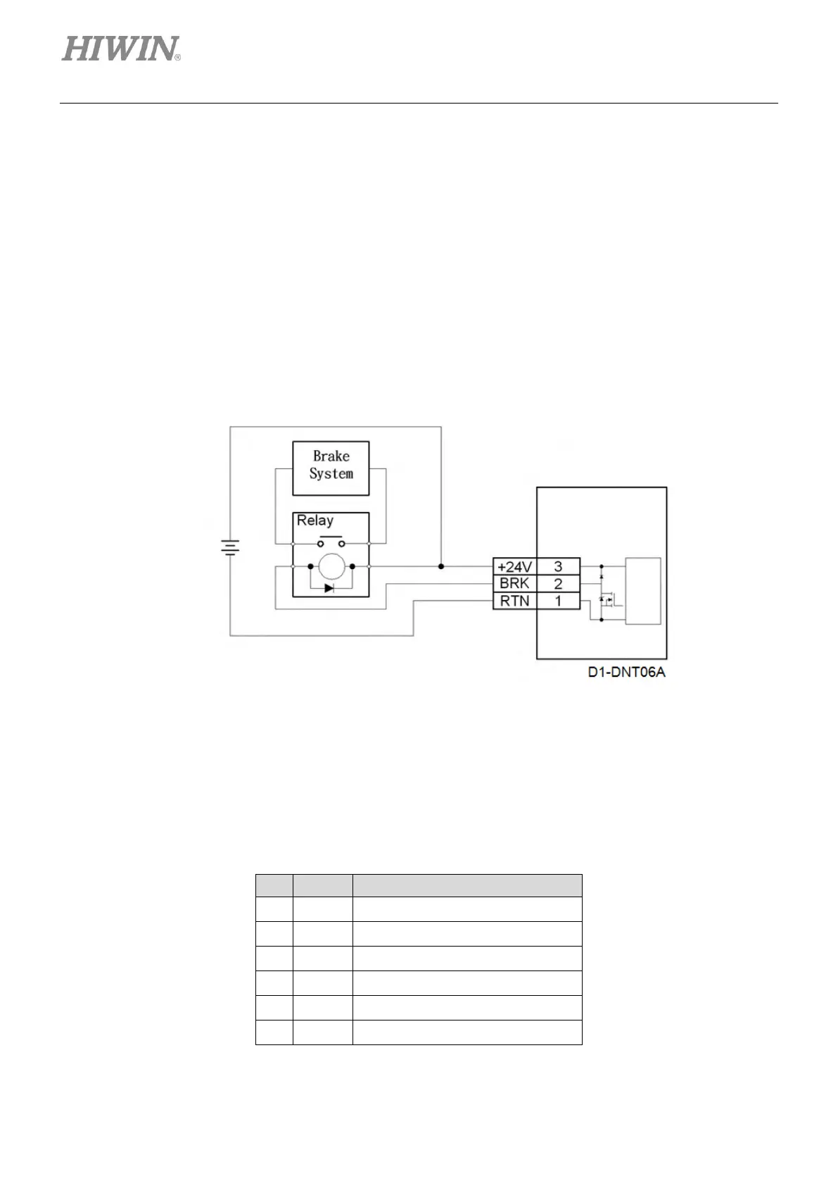
4.5 Wiring for control power and brake
For wiring 24 V DC control power and brake, please refer to figure 4.5.1. If there is no brake, connect +24
V to the +24 V pin (Pin3) of Wago standard connector 721-103, and connect 0 V to RTN pin (Pin 1). If
there is brake, connect brake output pin (BRK) with relay. When brake signal is output, the dynamic brake
or electromagnetic brake on motor can be activated via relay. The output for brake output (BRK) signal is
open-drain output which can withstand maximum voltage 40 V and maximum current 1 A. The default
output for brake output (BRK) signal is O4, but O4 can still be set for other output function. For setting
output function, pleas refer to section 5.4.2.
◼ Wiring for control power and brake
Figure4.5.1
4.6 RS232 communication (CN1)
(1) Pin assignment
Table4.6.1
mega-fabs
D1 series servo
drive