D1 Servo Drive User Manual Tuning
HIWIN MIKROSYSTEM CORP. 6-45
6.7.5 Spectrum analysis
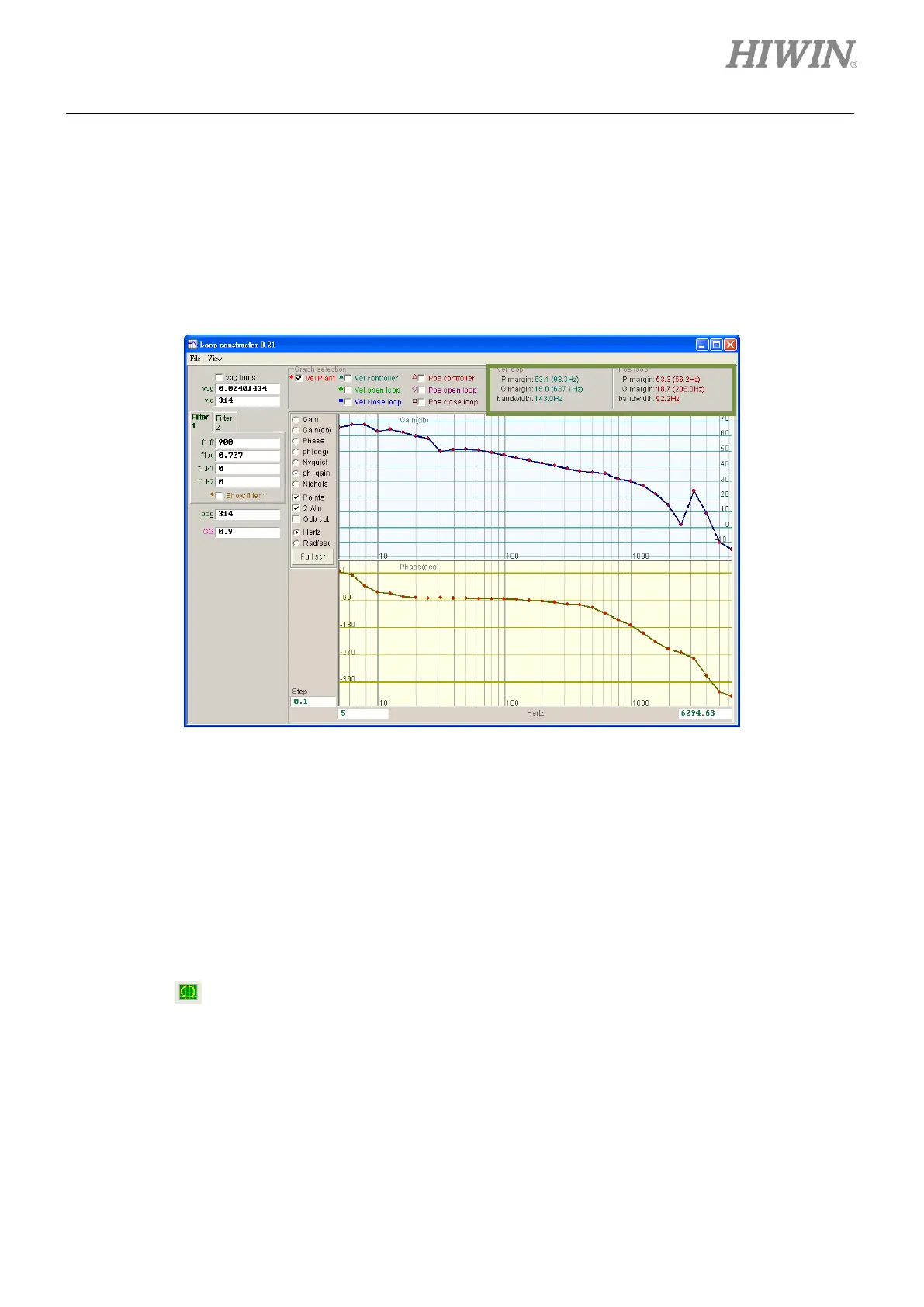
The gain margins, phase margins and bandwidth of velocity loop and position loop are provided in Loop
constructor window for user to adjust gains to simulate the stability of control system after gain tuning. In
Loop constructor window, P margin means phase margin and G margin means gain margin. For
further information of gain margin and phase margin, please refer to section 3.6.
Figure6.7.5.1 P margins and G margins in Loop constructor
6.8 Checking encoder signal
Encoder provides the servo drive with information such as position and angle to complete servo loop
control. User can check if encoder signal is normal or not via Lightening.
(1) Checking encoder signal
Click on in Performance center window or select Encoder test/tune from the submenu of
Tools to open the window for checking encoder signal. The windows for digital encoder and analog
encoder are different.