D1 Servo Drive User Manual Servo Drive Configuration
HIWIN MIKROSYSTEM CORP. 5-33
5.4 I/O setting
5.4.1 Digital inputs
D1 servo drive provides 10 digital inputs (I1~I6 and I9~I12). Nine digital inputs locate on connector CN2.
I5 locates on connector CN3 for motor over temperature, but it can still be set for other function. The
functions of I9 and I10 vary with the selected operation mode. In position mode, I9 and I10 cannot be
used as general-purpose inputs.
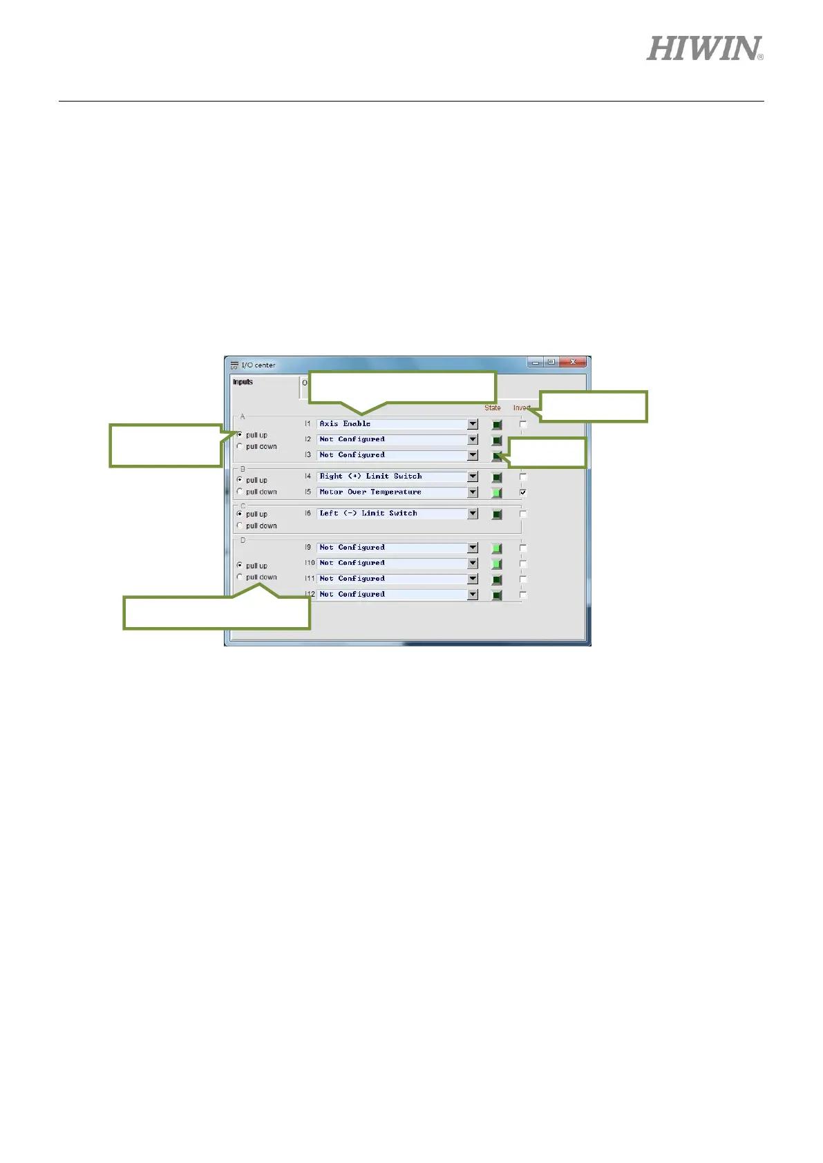
Figure5.4.1.1
(1) Setting trigger method
The digital inputs of D1 servo drive are divided into four groups, A, B, C and D group. Each group
can be set as pull up or pull down. The setting must based on the wiring of the servo drive. Select
pull up when the wiring is sink type. Select pull down when the wiring is source type. Refer to
section 4.7.1 for wiring examples and pay special attention to the wiring of group D. In position
mode, if controller is using optical coupler output (single-ended signal), the group must be set as pull
up. Otherwise, the servo drive cannot receive pulse signal.
Selection for input function
Trigger method of group D