Servo Drive Configuration D1 Servo Drive User Manual
5-34 HIWIN MIKROSYSTEM CORP.
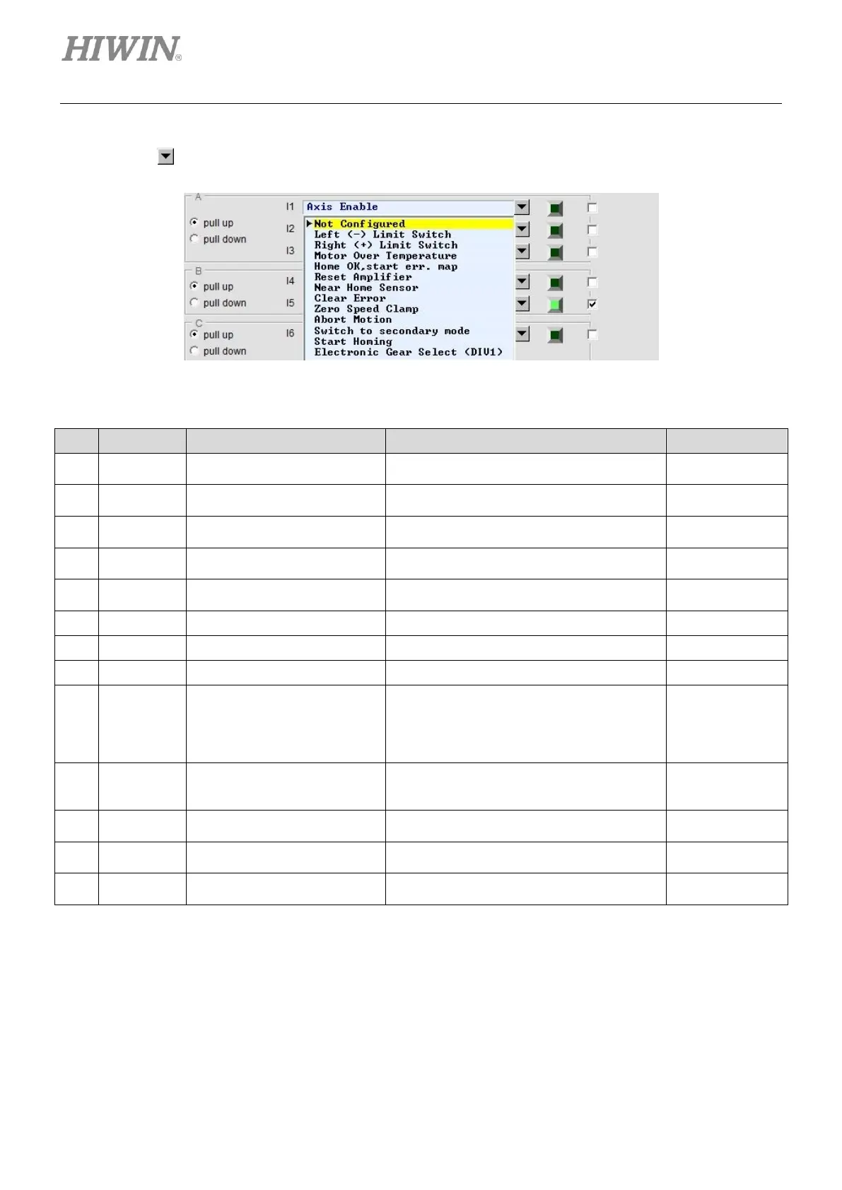
(2) Selection for input function
Click on , the drop-down list shown in figure 5.4.1.2 will appear.
Figure5.4.1.2
Table5.4.1.1 Input functions
Enable or disable axis.
Input I1 (Default)
Left hardware limit
Input I6 (Default)
Right hardware limit
Input I4 (Default)
Motor over temperature detection
Input I5 (Default)
Activate error map function after homing
completes.
Zero speed clamp
In velocity mode, when this signal is
received and the motor speed is slower than
the setting value, the motor will be stopped
at current position.
Emergency stop
When this signal is received, the motor stops
according to the emergency stop procedure.
Switch from first operation mode to second
operation mode.
Activate the built-in homing procedure in the
servo drive.
Electronic gear select (DIV1)
Electronic gear ratio selection for position
mode