EasyManua.ls Logo

Hiwin D1 - Page 115

Hiwin D1
307 pages
Print Icon
To Next Page IconTo Next Page
To Previous Page IconTo Previous Page
Loading...
D1 Servo Drive User Manual Servo Drive Configuration
HIWIN MIKROSYSTEM CORP. 5-35
MD20UE01-2109
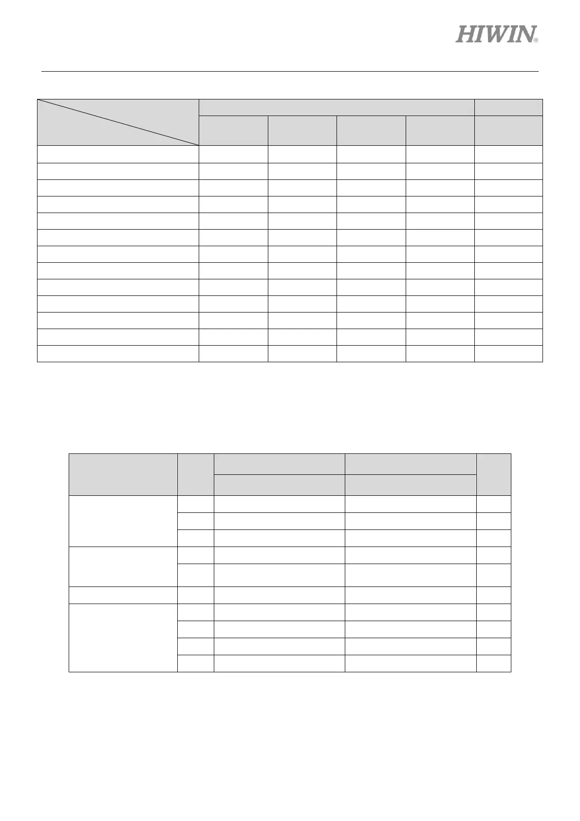
Table5.4.1.2 Supported input functions in each operation mode
Operation Mode
Input Function
Non-CoE Model
CoE Model
Position
Mode
Velocity
Mode
Force/torque
Mode
Stand-alone
Mode
Stand-alone
Mode
Axis enable
V
V
V
V
V
Left (-) limit switch
V
-
-
V
V
Right (+) limit switch
V
-
-
V
V
Motor over temperature
V
V
V
V
V
Home ok, start err. map
V
V
V
V
-
Reset amplifier
V
V
V
V
V
Near home sensor
V
V
V
V
V
Clear error
V
V
V
V
-
Zero speed clamp
-
V
V
-
-
Abort motion
-
-
-
V
-
Switch to secondary mode
V
V
V
V
-
Start homing
V
V
V
V
-
Electronic gear select (DIV1)
V
-
-
-
-
Note:
V means the input function is supported in the operation mode and can be assigned to I1~I12 (except I7 and
I8).
Table5.4.1.3 Default input functions of D1 servo drive
Pull Up/Pull Down
(Default)
Pin
Non-CoE Model
CoE Model
Invert
Default Signal
Default Signal
Group A: pull up
I1
Axis enable
Axis enable
No
I2
Abort motion
Left (-) limit switch
No
I3
Start homing
Right (+) limit switch
No
Group B: pull up
I4
Right (+) limit switch
Near home sensor
No
I5
Note
Motor over temperature/Not
configured
Motor over temperature/Not
configured
No
Group C: pull up
I6
Left (-) limit switch
Not configured
No
Group D: pull up
I9
Not configured
Not configured
No
I10
Not configured
Not configured
No
I11
Not configured
Not configured
No
I12
Not configured
Not configured
No
Note:
Depending on motor model, the default setting of I5 can be Motor over temperature or Not configured.

Table of Contents