Servo Drive Configuration D1 Servo Drive User Manual
5-36 HIWIN MIKROSYSTEM CORP.
(3) Indicator
If indicator becomes green, it means the set function is activated. If not, it means the function is not
activated.
(4) Logic setting
If Invert is selected, the trigger condition is inverted.
Applicable
Operation Mode
◆ Function
In stand-alone mode, when the input set for aborting motion is ON, the motor will decelerate at the
speed set in Dec. kill to a stop. Dec. kill can be set in Performance center.
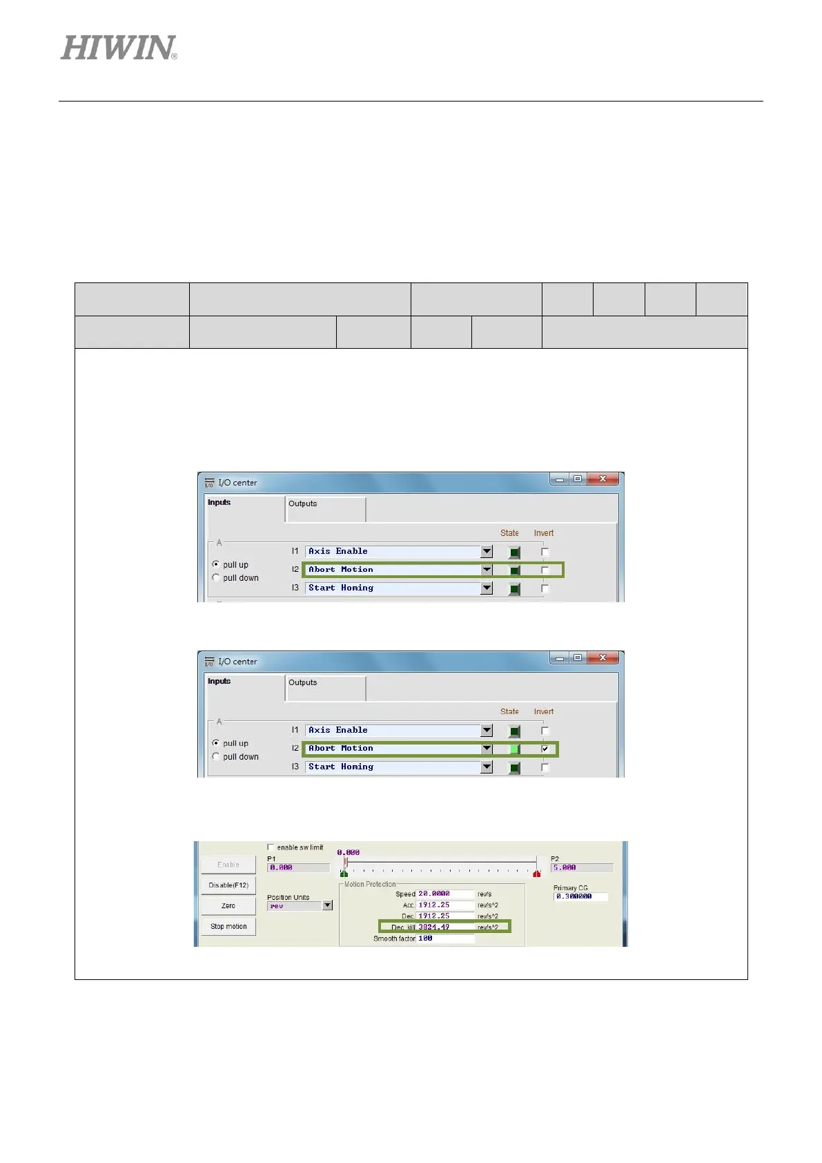
◆ Description
Set one input for aborting motion in I/O center. Use external signal to decelerate the motor at the speed
set in Dec. kill to a stop. In the figure below, I2 is set for aborting motion.
After external signal is input, the motor decelerates at the speed set in Dec. kill to a stop.
When State indicator becomes green, the servo drive ignores external pulse signal and decelerates
the motor at the speed set in Dec. kill to a stop.