Wiring D1 Servo Drive User Manual
4-16 HIWIN MIKROSYSTEM CORP.
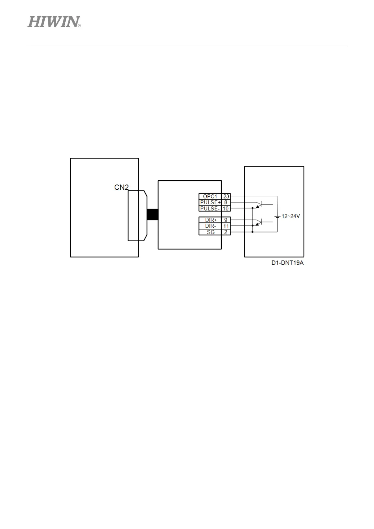
(2) Wiring example for controller sending single-ended signal
When D1 servo drive is used with controller sending single-ended signal, pulse adapter cable
(815AB3) must be connected to CN2. Refer to the figure below. The pin assignment of the pulse
adapter cable (815AB3) is the same as CN2, except for pin 23 and pin 22. Pin 23 is OPC1 and pin
22 has no function. The setting of single-ended signal must be completed in Lightening, please refer
to section 5.2.4. Set the trigger method of group D to pull-up in I/O center window, please refer to
section 5.4.1. The maximum input pulse frequency while using single-ended signal: pulse input
(500K pulses/s max.) and Quad A/B (2M counts/s max.).
Figure4.7.3.2
◼ Installation procedure
Step 1: Connect pulse adapter cable (815AB3) to CN2 of D1 servo drive.
Step 2: Connect HIWIN pulse control cable (LMACK30R) or self-made control cable with the
pulse adapter cable.
mega-fabs
D1 series servo drive
Pulse adapter cable
(815AB3)