D1 Servo Drive User Manual Wiring
HIWIN MIKROSYSTEM CORP. 4-17
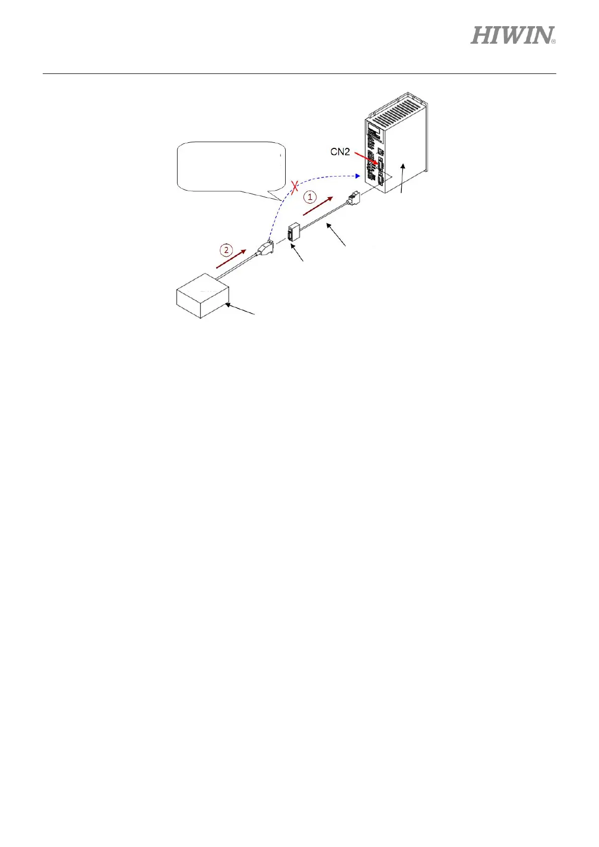
Figure4.7.3.3
◼ The using range of pulse adapter cable (815AB3)
(1) The cable can be used with PLC single-ended pulse control interface.
(2) The cable can be used with 12 V~24 V pulse control power.
(3) The maximum operating bandwidth is 500 Kpps.
◼ Note
(1) The pins 8, 9, 10, 11, 22 and 23 of pulse adapter cable (815AB3) are different from the pin
definition of D1 servo drive.
(2) Pulse adapter cable (815AB3) is used for interface conversion of pulse signal to improve
compatibility.
(3) In Lightening, go to Mode tab in Configuration center and select Single ended signals.
Refer to table 4.7.3.2 while connecting HIWIN pulse control cable (LMACK30R) with pulse
adapter cable (815AB3). When other cable is used, please refer to the signals on the female
end of the pulse adapter cable (815AB3).
Note:
Do not directly connect to
CN2 of D1 servo drive.
Pulse adapter cable
(815AB3)