Wiring D1 Servo Drive User Manual
4-18 HIWIN MIKROSYSTEM CORP.
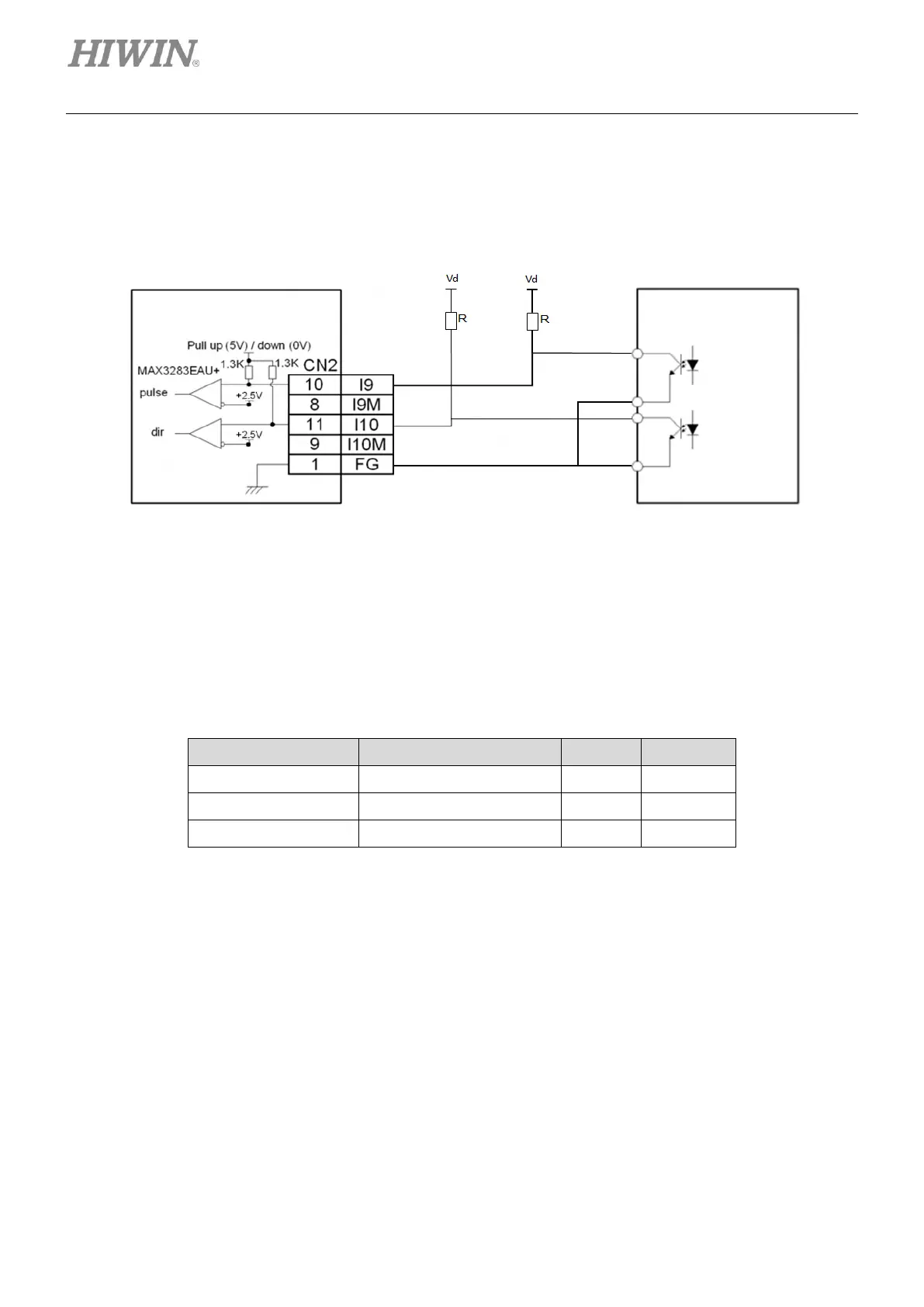
(3) Wiring example for controller sending single-ended signal and pulse adapter cable (815AB3) is not
used
External resistor is required to ensure the NPN transistor output of controller can meet the lowest
limit of breakover current, so operating velocity can be reached and pulse reception can be normal.
Figure4.7.3.4
Example:
If the pulse frequency output from controller needs to be 200 KHz, the internal NPN transistor needs
to be within the range of 12 mA IL (min) and 500 mA IL (max) (Refer to the datasheet of PLC.). The
external resistor must be: R= Vd/{IL(min)x(1+10%)-3.8mA}
Table4.7.3.1
Applicable Resistance (R)
mega-fabs
D1 series servo drive