EasyManua.ls Logo

Hiwin D1 - Page 61

Hiwin D1
307 pages
Print Icon
To Next Page IconTo Next Page
To Previous Page IconTo Previous Page
Loading...
D1 Servo Drive User Manual Wiring
HIWIN MIKROSYSTEM CORP. 4-19
MD20UE01-2109
Table4.7.3.2
The wire color table of HIWIN pulse control cable (LMACK30R) when connected with pulse
adapter cable (815AB3)
Pin
Wire Color
Signal on Female
End (815AB3)
Pin
Wire Color
Signal on Female
End (815AB3)
1
Brown
Frame Ground
14
Blue
O2
2
Brown/Black
Signal Ground
15
Blue/Black
O3
3
Red
I1
16
Light Blue
Encoder A
4
Red/Black
I2
17
Light Blue/Black
Encoder /A
5
Orange
I3
18
Purple
Encoder B
6
Orange/Black
I4
19
Purple/Black
Encoder /B
7
Green
I6
20
Gray
Encoder Z
8
Pink
PULSE+
21
Gray/Black
Encoder /Z
9
Yellow
DIR+
22
White/Red
-
10
Pink/Black
PULSE-
23
Black
OPC1
11
Yellow/Black
DIR-
24
White
Analog Ref In (+)
12
Green/Black
I11
25
White/Black
Analog Ref In (-)
13
Light Green
O1
26
Light
Green/Black
I12
case
-
Shield
-
-
-
Note:
This table is not applicable to CN2 on D1 servo drive. Pin 23 on the female end of pulse adapter cable
(815AB3) is for 12~24 V input, but CN2-Pin 23 on D1 servo drive is for 0 V reference.
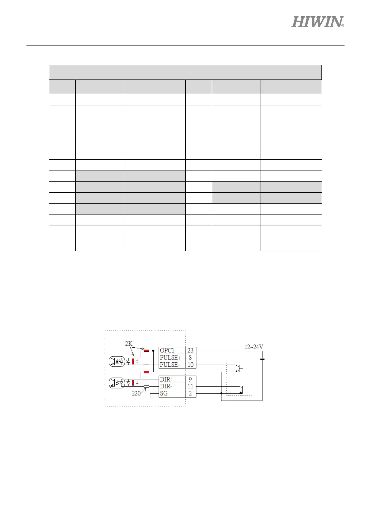
Wiring diagram for position control
(1) Do not use external resistor
Figure4.7.3.5
Pulse adapter cable (815AB3)

Table of Contents

Related product manuals