Servo Drive Configuration D1 Servo Drive User Manual
5-42 HIWIN MIKROSYSTEM CORP.
(3) Logical value
The logical value of each output is displayed. The displayed value can be TRUE or FALSE.
(4) Invert output voltage
If needed, select Invert voltage to invert the polarity of output voltage. Please be noted the internal
logical value of the servo drive will not be affected.
(5) Output voltage
The voltage level of the output pin will be displayed for user to check if the signal received by
controller is correct.
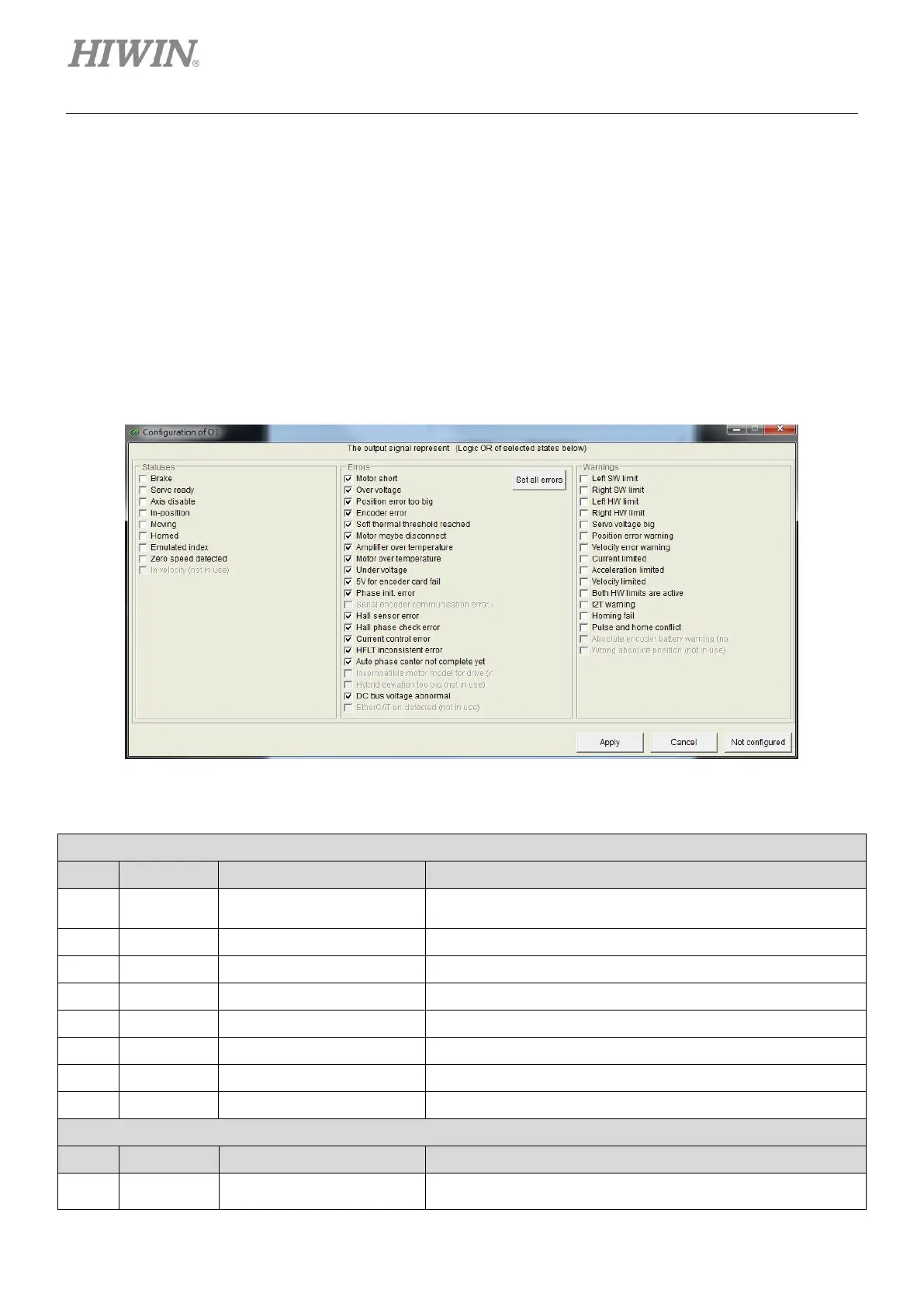
Figure5.4.2.2
Table5.4.2.1
Brake signal
If Brake is selected, other output functions cannot be set.
Emulated Z-phase index signal
Zero speed detection signal
Normally all the selections in this category are set. (Click on
Set all errors button.) User can also have his own setting