LCD Display D1 Servo Drive User Manual
7-10 HIWIN MIKROSYSTEM CORP.
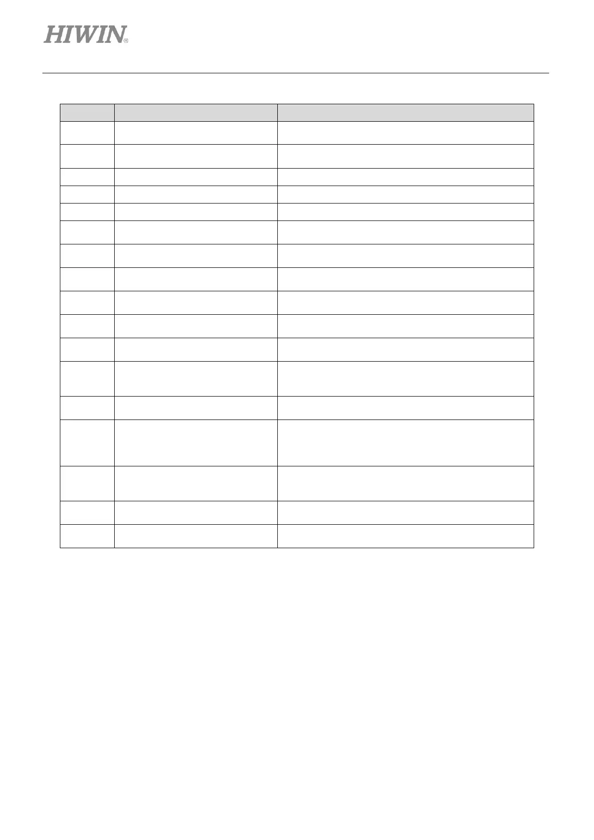
Table7.4.1 Table of commonly-used parameters (Set parameters based on actual situation.)
Set the maximum output acceleration of motor during
motion.
Set the maximum output deceleration of motor during
motion.
Set the maximum velocity of motor during motion.
Set the cutoff frequency of filter 1 in closed loop.
Set the cutoff frequency of filter 2 in closed loop.
The servo stiffness is stronger as servo gain is higher.
The servo stiffness is weaker as servo gain is lower.
The numerator of electronic gear
ratio
The numerator of electronic gear ratio (output)
The denominator of electronic
gear ratio
The denominator of electronic gear ratio (input)
Scaling of analog voltage
command (velocity mode)
The scaling of velocity command
Set the corresponding velocity of unit voltage.
Scaling of analog voltage
command (force/torque mode)
The scaling of current command
Set the corresponding current of unit voltage.
Input range: 1~500
Larger smooth factor can have smoother motion profile.
0: Quadrature (AqB)
1: Pulse/Direction
2: Pulse up/Pulse down (CW/CCW)
Inversion of pulse command
0: Do not invert.
1: Invert.
0: Stand-alone mode
1: Position mode
2: Velocity mode
3: Force/torque mode
Switching between single-ended
pulse signal and differential pulse
signal
0: Single-ended
1: Differential
0: Do not invert.
1: Invert.
0: Do not invert.
1: Invert.
Note:
For the corresponding parameter of each LCD number, please refer to table 7.4.3.1.