D1 Servo Drive User Manual LCD Display
HIWIN MIKROSYSTEM CORP. 7-35
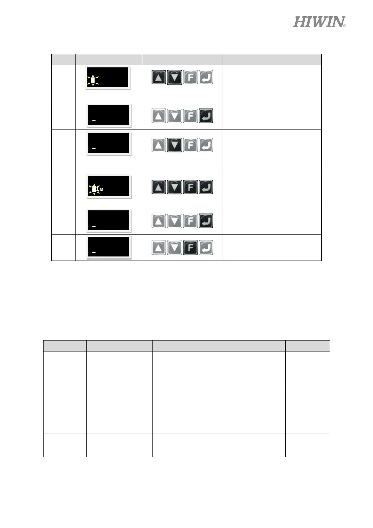
Press Up key or Down key to set
command input type.
Note:
In this example, analog voltage
command input is set.
Press Enter key to complete
command input type setting.
Press and hold Down key to go
to LCD No. 83 page which is the
setting page for the scaling of
velocity command (Refer to the
note below.).
Press Enter key. Then set the
scaling of velocity command. (To
invert voltage command or PWM
command, add a negative sign in
front of the scaling.)
Press Enter key to complete the
setting of the scaling of velocity
command.
Press and hold F key to go to
LCD No. +++ page which is the
commonly-used parameter area.
The setting method of the deadband of velocity command (LCD No. 084) is the same as that of the
scaling of velocity command (LCD No. 083).
Note:
Refer to the table below for the parameter setting of command input type.
Table7.6.2.3
The command input type of velocity mode
and force/torque mode
0: Analog
1: PWM 50%
2: PWM 100%
The scaling of velocity command
Input the corresponding velocity of unit
voltage or the corresponding maximum
velocity of full PWM.
(LM (DD) unit: mm/s (rpm) = 1V or mm/s
(rpm) = full PWM)
The deadband of velocity command
Velocity command is 0 when input voltage is
smaller than this setting value. (Unit: volt)