Operation Principles D1 Servo Drive User Manual
3-10 HIWIN MIKROSYSTEM CORP.
B. If
intersects with the negative real axis between 0 and -1,
and
. When the Nyquist plot intersects with the negative real axis between 0 and -1 at
any frequency, the system is stable as loop gain increases.
C. If
is on (-1, j0),
and
. When
is on (-1, j0). It means
and the system has reached the boundary of instability. Loop gain must not be
increased anymore.
D. If
passes (-1, j0),
and
. When
passes (-1, j0),
. Loop gain must be decreased to have stable system.
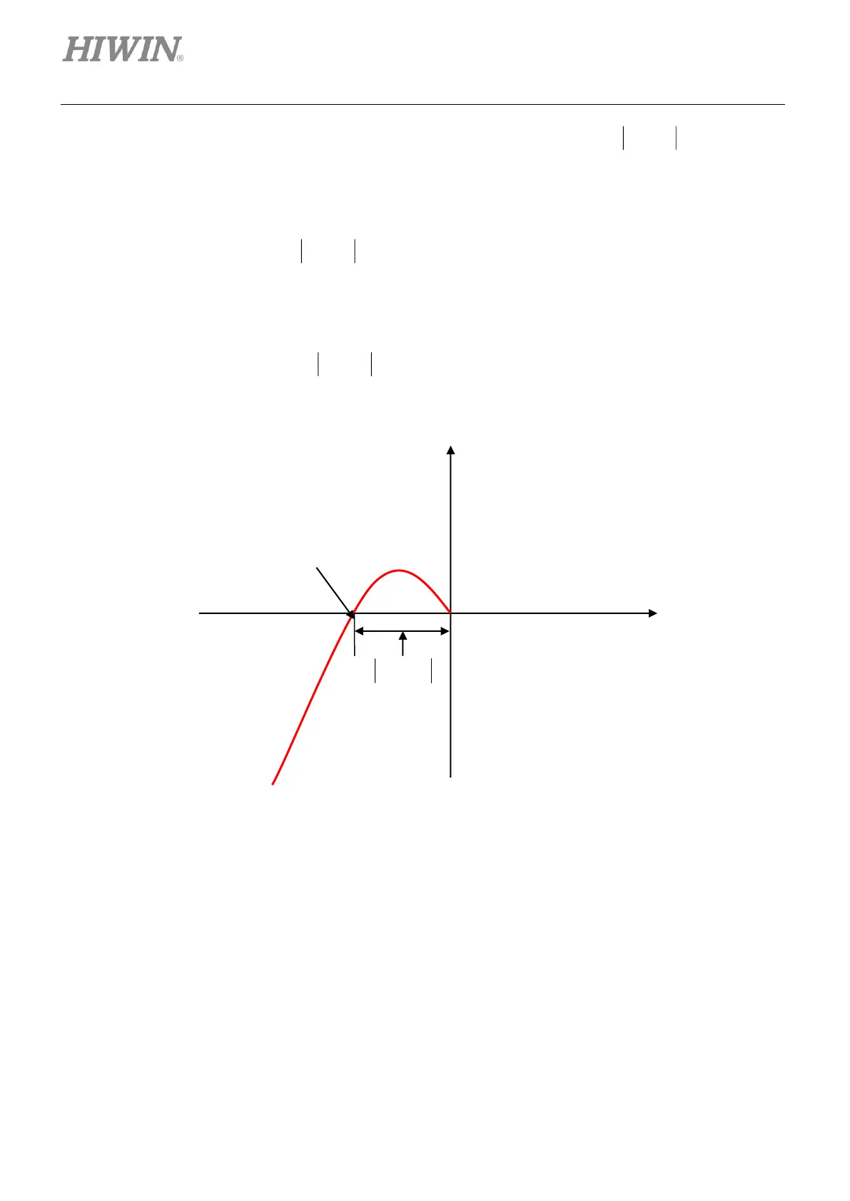
Figure3.6.1.1 Gain margin