Configuration
100 UDC3500 Universal Digital Controller Product Manual 3/07
Function Prompt
Lower Display
Selections or
Range of Setting
Upper Display
Parameter
Definition
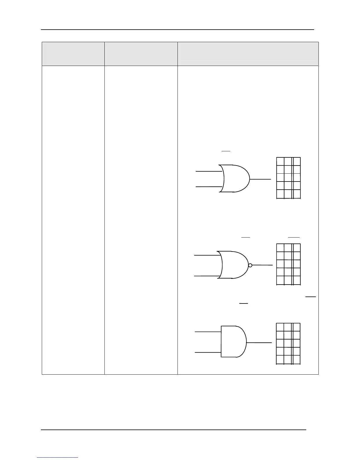
GATE(n)TYP
(n = 1, 2, 3, 4, or 5)
GATE TYPE—In digital logic, there are only two
states that can be present:
“0” – OFF or “1” – ON
Listed are definitions of the gates available and their
truth table which indicate what happens to the
Output with regard to the state of the Inputs.
NOT USED
NOT USED—No Selection
OR
OR—With this gate, if Input A OR Input B is ON,
then the Output will be ON. Also, if both Inputs are
ON, the Output will also be ON because it takes any
one Input being ON
to make the Output
INPUT A
INPUT B
OR
A
B
0
1
OUTPUT (Y)
0
0
0
0
1
1
1
1
1
1
NOR
NOR—The NOR gate is similar to the OR gate,
except that the Output is inverted. It is exactly
opposite of the OR gate and is referred to as NOT
OR or NOR.
If Input A or Input B are ON
, the Output is OFF.
INPUT A
INPUT B
NOR
A
B
0
1
OUTPUT (Y)
0
0
0
0
1
1
1
0
0
1
AND
AND—With this gate, if Input A AND Input B are ON,
then the Output will be ON
; so that any single Input
change will not cause the Output to change unless
the other Input is already ON.
AND
INPUT A
INPUT B
OUTPUT (Y)
A
B
0
1
0
0
0
0
1
1
1
0
0
1

 Loading...


