Motion Overview 406
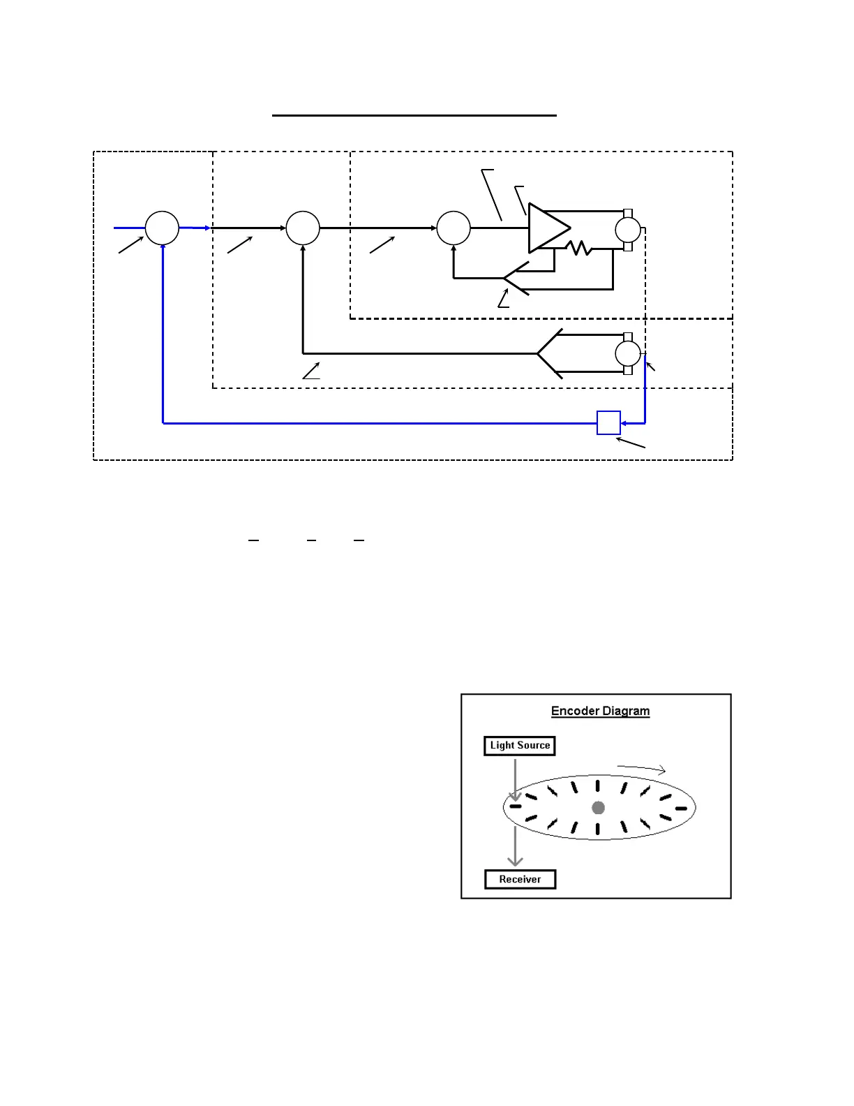
Typical Velocity and Position Loop System
The Motion Command starts as Digital Output within the control and then is converted to a +/- 10VDC
Analog Output for use by the motors. This conversion of the Motion Command within the control is
referred to as the DAC (Digital to Analog Converter) Output and is performed by the Motion Control
Card. The Analog Output when it comes out of the control is sent to a drive amplifier that then steps
up the voltage output to the motor and creates motion. Also, there is usually a linear relationship
between the voltage sent and the machine speed (i.e. 10 volts = maximum machine speed, 5 volts =
half max machine speed). Additionally, the polarity of the output (DAC Polarity +/-) to the amplifier
will dictate the direction of the motor rotation. In most applications and in the following application
description the feedback device is an Encoder.
1a) What is an Encoder?
Essentially, an Encoder is a feedback device
that provides signal pulses as the motor turns.
The diagram at the right illustrates the basic
concept of an Encoder. Although this does
not represent all Encoder / feedback device
technology, this illustration provides a visual
aid to help understand the process.
The illustration shows a disk with small holes
cut out along the outer edge. The light source
provides a beam of light projected downward
through the holes in the disk. As the disk
turns on the end of the motor shaft, the light passes through the disk creating pulses.
The Receiver below the disk picks up the pulsed light source and sends that
feedback to the control.
Current
Command or
Velocity Error
Signal