Mariner™ 530
The Mariner™ Shape Cutting Control is designed with all machine interface connections passing
through the pedestal mount at the base of the enclosure. Motion and I/O are supported via the fiber
optic communication ring of the SERCOS Interface™.
The information contained in this section is intended to provide the basic information for connection of
the Mariner™ Shape Cutting Control to the cutting table. Each machine interface will vary slightly
based on the cutting table configuration and features.
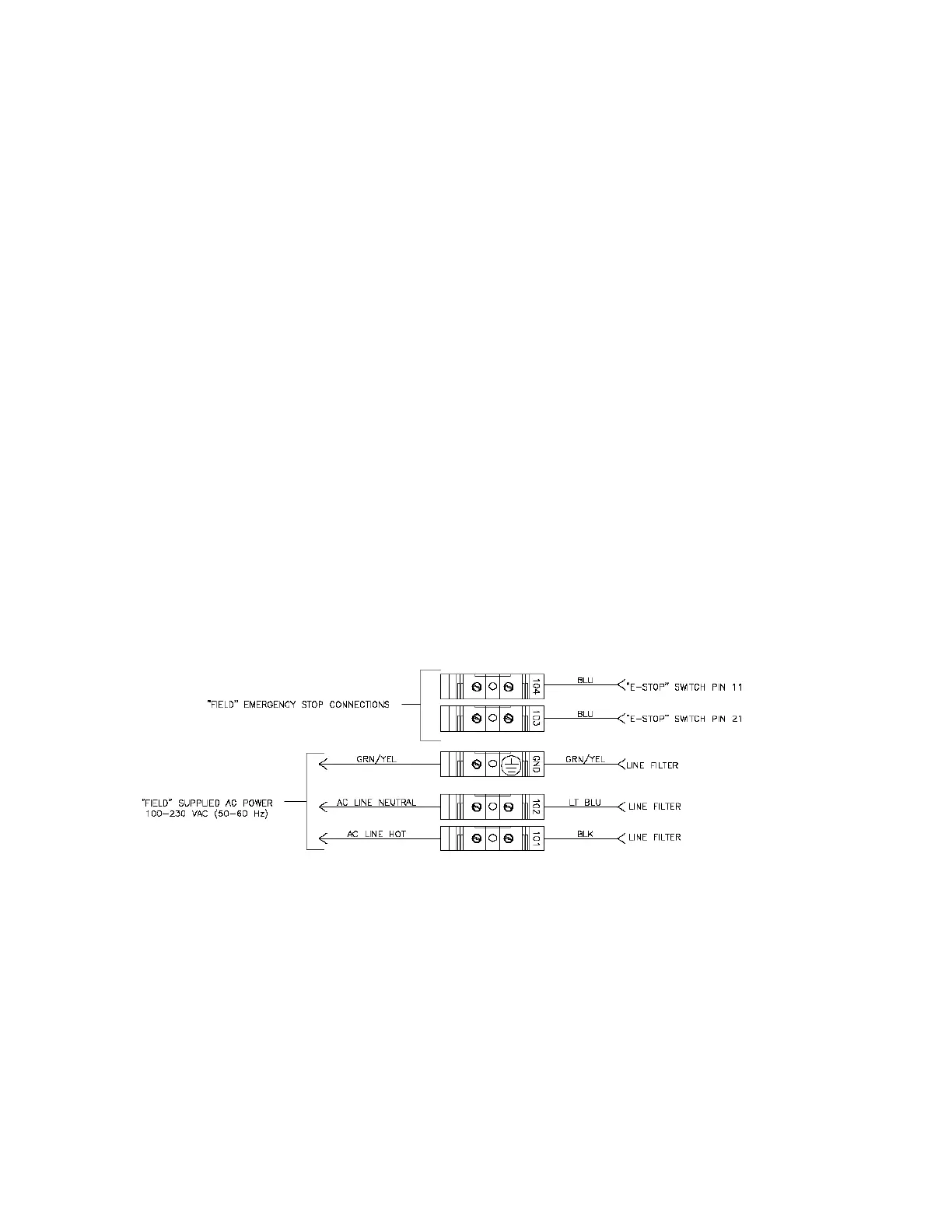
AC Input Pinout
TB connector Description
101 110VAC or 220VAC Input (Hot)
102 110VAC or 220VAC Input (Neutral)
AC Power Ground
Recommended Wire
14 AWG or greater
E-Stop
The E-stop Switch provides normally open contacts rated at 20VAC/500mA minimum to 250VAC/6A
maximum.
TB connector Description
103 Contact Closure
104 Contact Closure
Diagram Location Din-02
SERCOS Motion and I/O
As noted previously, Motion and I/O are supported via the fiber optic communication ring of the
SERCOS Interface™. Digital and Analog I/O are supported.
Motion is controlled through address assignments for the axes. Inputs and Outputs work on a similar
assignment in SERCOS and may be mapped at the I/O configuration screen.
Details for wiring the motion and I/O are specific to the specific SERCOS hardware being used.
Please refer to the appropriate supplier for interfacing information.