Voyager™ III 527
SERCOS to Analog Conversion Card
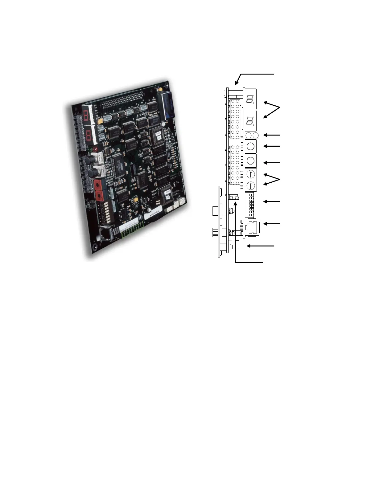
`
Decimal Read Out
The 7 segment display indicates SERCOS ring phases status 1-4. Additionally, the 2 decimal points
in the 7 segment display indicate phase condition for the SERCOS ring and are on immediately after
CNC boot up and reset. They remain on until the ring is successfully phased up to phase 4. After
that the decimal points remain off even if the ring drops from phase 4. With this approach, if the
SERCOS ring is not running, you can determine if the ring has ever made it to phase 4 during that
power on cycle. This assumes the card has not been reset or lost power.
Status Indicator Lights
A Red and Green light are provided to indicate status of the SERCOS ring. Red indicates a Fault and
Green indicates a RUN status.
Drive Address Rotary Hex Switches
Factory settings are as follows:
For Axes 1 and 2: SW1 = 0, SW2 = 1
For Axes 3 and 4: SW1 = 0, SW2 = 3
For Axes 5 and 6: SW1 = 0, SW2 = 5
For Axes 7 and 8: SW1 = 0, SW2 = 7
For Axes 9 and 10: SW1 = 0, SW2 = 9
For Axes 11 and 12: SW1 = 0, SW2 = B
Note: Markings on backdoor machine interface for Axes are zero based.