Edge Ti™ 500
Switch SW1-3
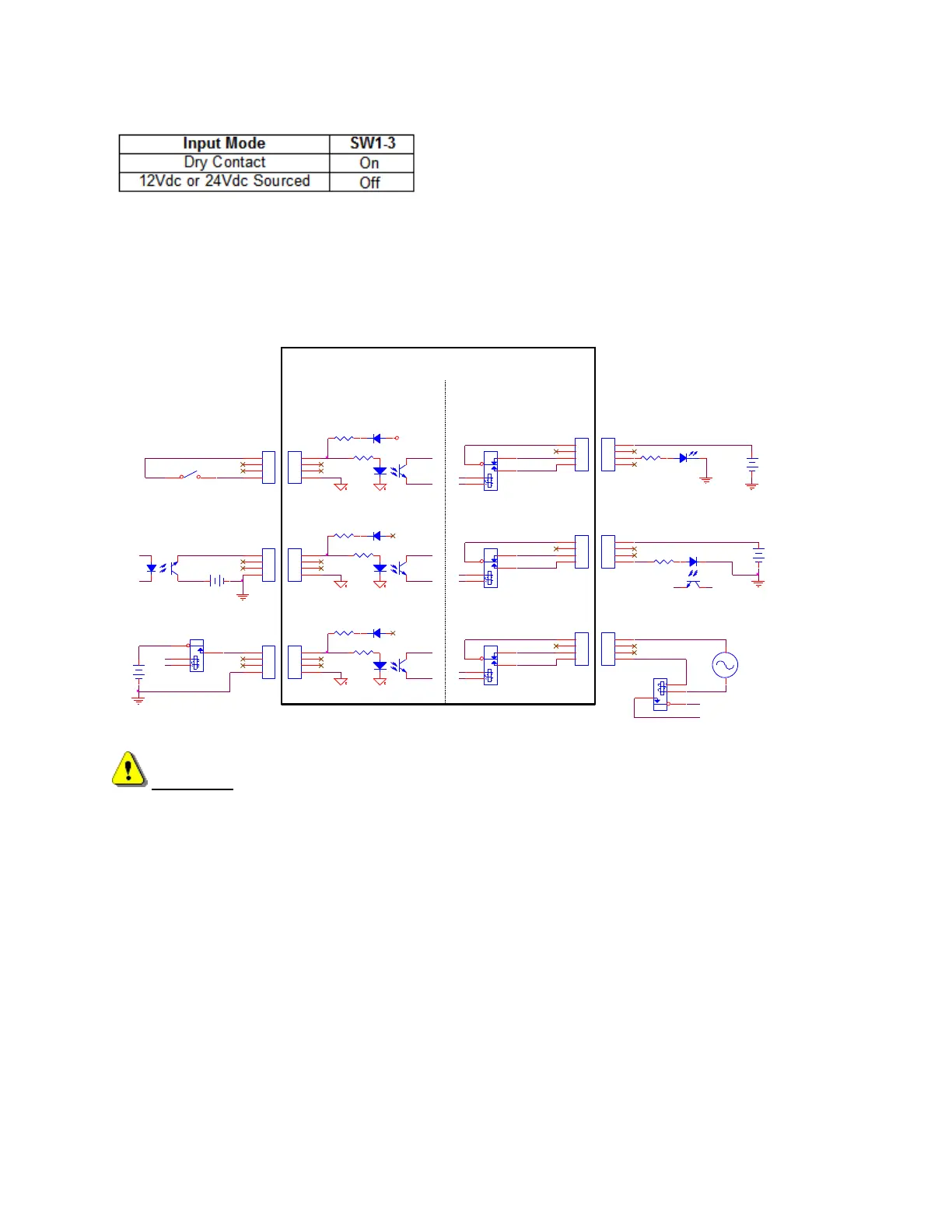
I/O Interface
The following illustration shows the details of connecting the I/O to common circuitry. All outputs are
relay contacts rated at 1 AMP 250VAC maximum
RESISTOR
LED
12V
Use External +12V Supply
& normally Closed Contact
24V
+
GND_External
+
RESISTOR
Use External +5V Supply
& normally Open Contact
RELAY SPDT
Normal Sourced Inputs
Use External +24V Supply
GND_External
5V
NC
NO
+
COM
12V
GND_External
GND_External
RELAY
GND
External Circuitry
OPTO ISOLATOR
+
Use External 120 Vac
& normally open contact
RELAY SPDT
COM
NO
NC
3900
RELAY SPDT
NC
COM
NO
Dry Contact Inputs
Note: Logic Level Reversal
SWITCH
Normal Sourced Inputs
DIP Sw 1-C Open
Edge-Ti Internal Circuitry
Outputs
External Circuitry
OPTO ISOLATOR
Inputs
GND
3900
Example Inputs
3900
GND
3900
3900
Open
Open
+24V Field
3900
RELAY
120 Vac
Normal Sourced Inputs
Use External +12V Supply
Normal Sourced Inputs
DIP Sw 1-C Open
Dry Contact Inputs
DIP Sw 1-C Closed
GND_External
Example Outputs
WARNING! Do not exceed 24Vdc or 10mA into any optoisolator input. Use care to observe the
correct signal polarities or damage may occur! Do not exceed 250 Vac or 1 Amp through any relay
output.