Edge Ti™ 498
Machine Interface
The information provided here is the basic information for connection of the shape cutting control to
the cutting table. Each machine interface will vary slightly based on the cutting table configuration
and features. Additionally, I/O pinout information may vary slightly based on the configuration of the
selected I/O and their locations. Changes to the I/O configuration may be made in the password
protected I/O screen. All controls are shipped with a default selection of Inputs and interface
locations for the selected control Interface (I/O) configuration. Installation and service should only be
performed by a qualified service technician.
The rear panel of the control has several cable connectors to connect the control to power, I/O and
communication ports. These connectors are clearly labeled as to their function.
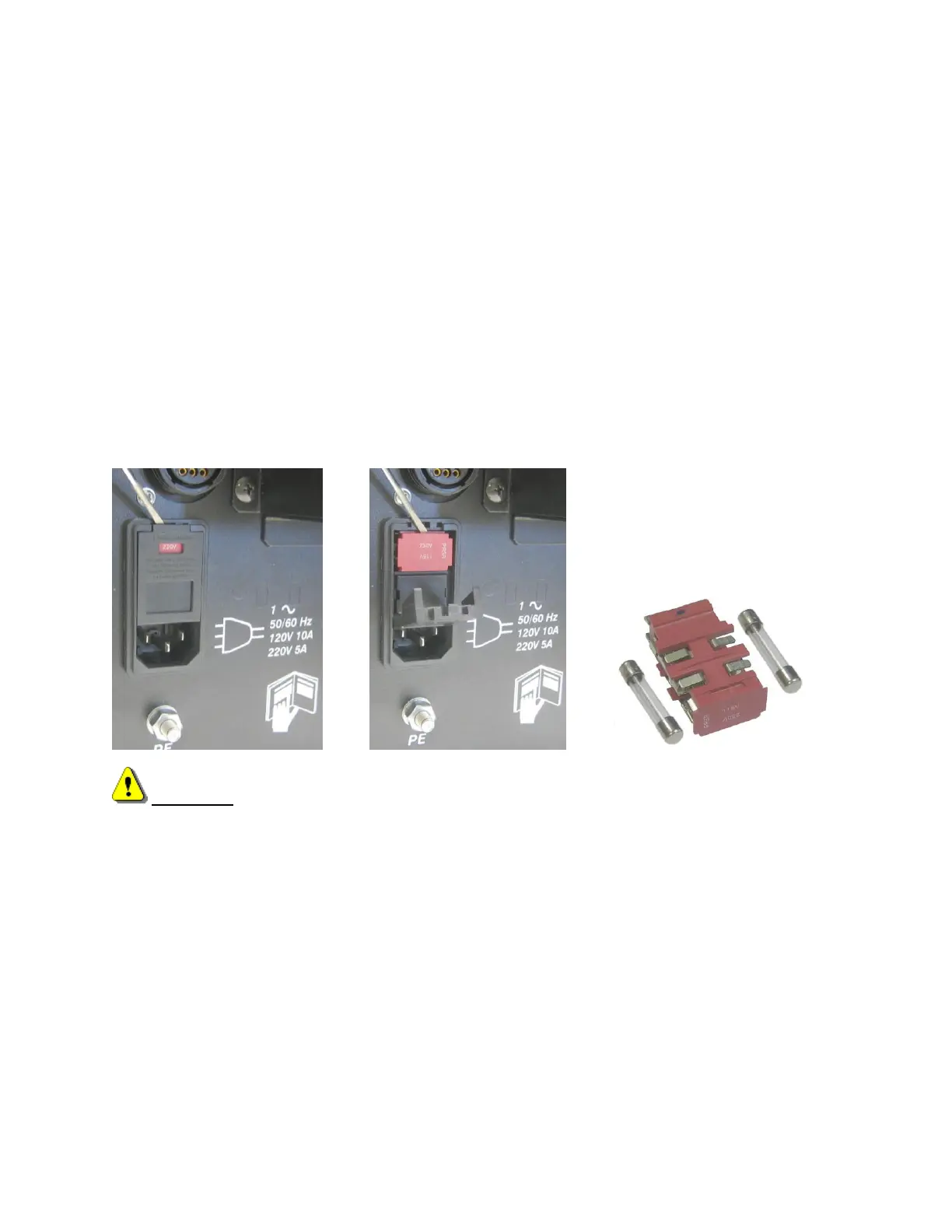
AC Input
The AC power cable is inserted into the AC power connector and plugged into a standard 3-way 115
or 230 volt outlet. The AC Power connector contains an integral fuse module and line filter. AC input
power can be selected by the user by changing position of the fuse module so that the selected
voltage is displayed.
WARNING! Ensure proper orientation of fuse module for input power before applying power to
the CNC. Component damage could occur with incorrect voltage setting.
Recommended AC Fuses
Different fuse ratings are recommended based on incoming voltage selected.
Voltage Input: 120Vac uses 8 amp (slow blow) Littlefuse part #313008
Voltage Input: 220Vac uses 5 amp (slow blow) Littlefuse part #313005
Size: ¼” x 1¼” or 5mm x 20MM fuse can be used
Serial Port
Please refer to the Ports Information section of the Installation Guide for additional information on
configuration of Serial ports for communication.
A remote communications link can be connected to one of the two serial ports and an external ground
(PE) lug for earth grounding of the unit is also provided.