For bonded configuration mode, the low speed parallel clock output of the master CGB
is used and the local CGB within each channel is bypassed. For non-bonded
configurations, the master CGB also provides a high speed serial clock output to each
channel without bypassing the local CGB within each channel.
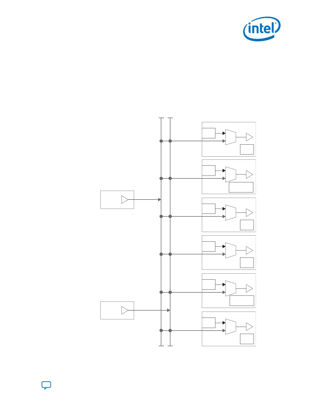
The x6 clock lines also drive the xN clock lines which route the clocks to the
neighboring transceiver banks.
Figure 125. x6 Clock Lines
CGB
Ch 4
CDR
CGB
Ch 3
CDR
CGB
Ch 2
CGB
Ch 1
CDR
CGB
Ch 0
CDR
CGB
Ch 5
Master
CGB
Master
CGB
x6
Top
x6
Bottom
x6
Network
CMU or CDR
CMU or CDR
3. PLLs and Clock Networks
UG-20070 | 2018.09.24
Send Feedback
Intel
®
Cyclone
®
10 GX Transceiver PHY User Guide
213