3.11. Using PLLs and Clock Networks
In Cyclone 10 GX devices, PLLs are not integrated in the Native PHY IP core. You must
instantiate the PLL IP cores separately. Unlike in previous device families, PLL merging
is no longer performed by the Quartus Prime software. This gives you more control,
transparency, and flexibility in the design process. You can specify the channel
configuration and PLL usage.
Related Information
PLLs and Clock Networks on page 198
3.11.1. Non-bonded Configurations
In a non-bonded configuration, only the high speed serial clock is routed from the
transmitter PLL to the transmitter channel. The low speed parallel clock is generated
by the local clock generation block (CGB) present in the transceiver channel. For non-
bonded configurations, because the channels are not related to each other and the
feedback path is local to the PLL, the skew between channels cannot be calculated.
Also, the skew introduced by the clock network is not compensated.
3.11.1.1. Implementing Single Channel x1 Non-Bonded Configuration
In x1 non-bonded configuration, the PLL source is local to the transceiver bank and
the x1 clock network is used to distribute the clock from the PLL to the transmitter
channel.
For a single channel design, a PLL is used to provide the clock to a transceiver
channel.
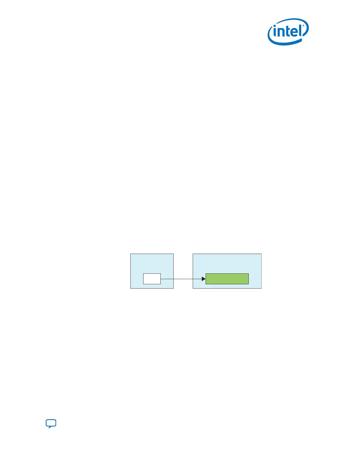
Figure 138. PHY IP Core and PLL IP Core Connection for Single Channel x1 Non-Bonded
Configuration Example
Transceiver PLL
Instance (5 GHz)
PLL
Native PHY Instance
(1 CH Non-Bonded 10 Gbps)
TX Channel
To implement this configuration, instantiate a PLL IP core and a PHY IP core and
connect them together as shown in the above figure.
Steps to implement a Single Channel x1 Non-Bonded Configuration
1. Instantiate the PLL IP core (ATX PLL, fPLL, or CMU PLL) you want to use in your
design.
2. Configure the PLL IP core using the IP Parameter Editor.
• For ATX PLL IP core, do not include the Master CGB.
• For fPLL IP core, set the PLL feedback operation mode to direct.
• For CMU PLL IP core, specify the reference clock and the data rate. No special
configuration rule is required.
3. Configure the Native PHY IP core using the IP Parameter Editor .
3. PLLs and Clock Networks
UG-20070 | 2018.09.24
Send Feedback
Intel
®
Cyclone
®
10 GX Transceiver PHY User Guide
231