You can initiate the recalibration process by writing to the specific recalibration
registers. You must also reset the transceivers after performing user recalibration. For
example, if you perform data rate auto-negotiation that involves PLL reconfiguration,
and PLL and channel interface switching, then you must reset the transceivers.
The proper reset sequence is required after calibration. Intel recommends you use the
Transceiver PHY Reset Controller IP which has tx_cal_busy and rx_cal_busy
inputs and follow Intel's recommended reset sequence. You need to connect
tx_cal_busy and rx_cal_busy from the Native PHY IP core outputs to the reset
controller inputs in your design. Reset upon calibration is automatically processed
when you perform user recalibration.
Related Information
• Implementing PLL Cascading on page 240
• Implementing PLL Feedback Compensation Bonding Mode on page 237
• Recommended Reset Sequence on page 246
• Transmit PLLs Spacing Guidelines when using ATX PLLs and fPLLs on page 200
7.4.2. User Recalibration Sequence
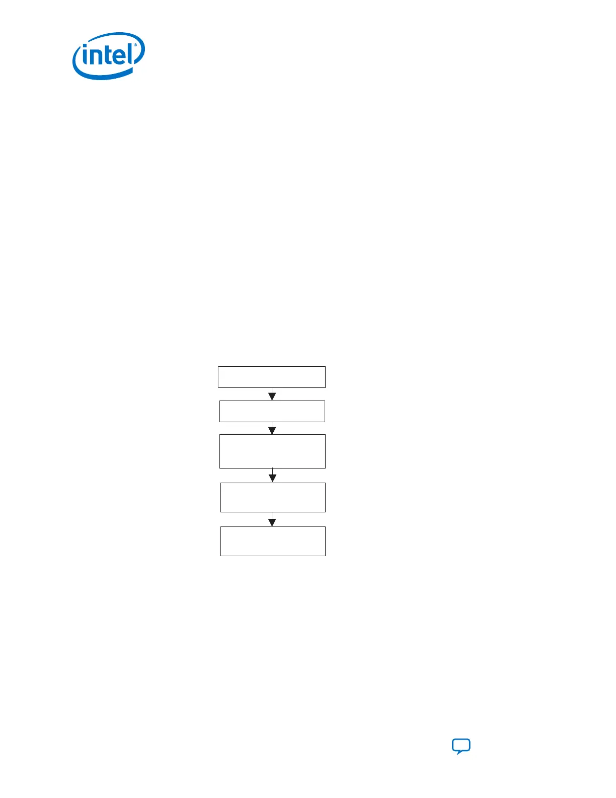
Figure 224. User Recalibration Sequence for ATX PLL, fPLL and Native PHY IP (RX PMA /
TX PMA)
ATX PLL Calibration
fPLL Calibration
PMA RX
Calibration (1)
PMA TX
Calibration (2)
Calibration
Done
Note:
(1) If you are using the CDR/CMU PLL, you need to trigger RX
PMA recalibration.
(2) If you are using the CMU PLL as TX PLL, you need to trigger
RX PMA recalibration followed by a TX PMA recalibration.
User recalibration requires access to the internal configuration bus and calibration
registers through the Avalon-MM reconfiguration interface. Follow the recalibration
example steps detailed in Calibration Example to perform a user recalibration process
for each ATX PLL IP, fPLL IP and Native PHY IP (RX PMA / TX PMA).
Related Information
Calibration Example on page 385
7. Calibration
UG-20070 | 2018.09.24
Intel
®
Cyclone
®
10 GX Transceiver PHY User Guide
Send Feedback
384