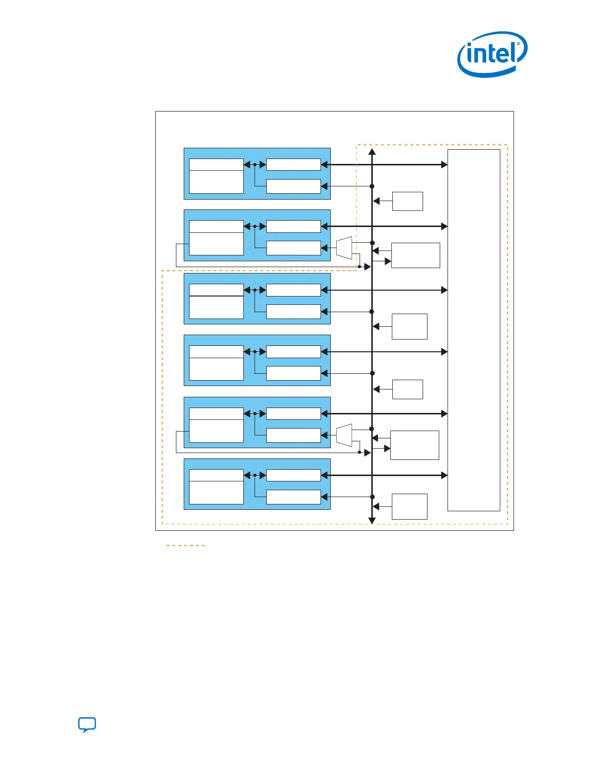
Figure 5. Transceiver Bank Architecture
PMA
Channel PLL
(CDR Only)
PCS
Local CGB5
CH5
PMA
Channel PLL
(CMU/CDR)
PCS
Local CGB4
CH4
PMA
Channel PLL
(CDR Only)
PCS
Local CGB3
CH3
PMA
Channel PLL
(CDR Only)
PCS
Local CGB2
CH2
PMA
Channel PLL
(CMU/CDR)
PCS
Local CGB1
CH1
PMA
Channel PLL
(CDR Only)
PCS
Local CGB0
CH0
FPGA Core
Fabric
Clock
Distribution
Network
Six-Channel Transceiver Bank
fPLL1
Master
CGB1
Master
CGB0
ATX
PLL0
ATX
PLL1
fPLL0
Legend:
4-Channel transceiver bank
Note: This figure is a high level overview of the transceiver bank architecture. For details
about the available clock networks refer to the PLLs and Clock Networks chapter.
Related Information
PLLs and Clock Networks on page 198
1.2.2. PHY Layer Transceiver Components
Transceivers in Intel Cyclone 10 GX devices support both Physical Medium Attachment
(PMA) and Physical Coding Sublayer (PCS) functions at the physical (PHY) layer.
1. Intel
®
Cyclone
®
10 GX Transceiver PHY Overview
UG-20070 | 2018.09.24
Send Feedback
Intel
®
Cyclone
®
10 GX Transceiver PHY User Guide
11