Related Information
Cyclone 10 GX Enhanced PCS Architecture on page 283
5.3.1.6. TX Bit Slip
The TX bit slip allows the word boundary to be controlled by
tx_std_bitslipboundarysel. The TX bit slip feature is used in applications, such
as CPRI, which has a data rate greater than 6 Gbps. The maximum number of the
supported bit slips is PCS data width-1 and the slip direction is from MSB to LSB and
from current to previous word.
5.3.2. Receiver Datapath
5.3.2.1. Word Aligner
The word aligner receives the serial data from the PMA and realigns the serial data to
have the correct word boundary according to the word alignment pattern configured.
This word alignment pattern can be 7, 8, 10, 16, 20, 32 and 40 bits in length.
Depending on your PCS-PMA interface width, the word aligner can be configured in
one of the following modes:
• Bit slip
• Manual alignment
• Synchronous state machine
• Deterministic latency
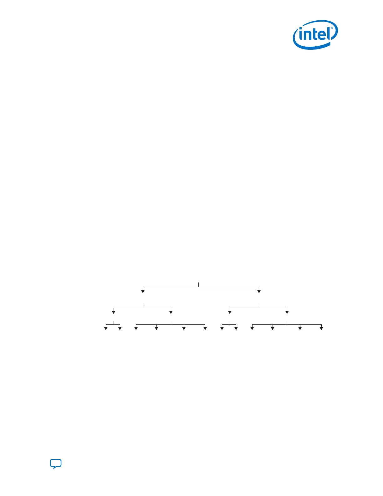
Figure 202. Word Aligner Conditions and Modes
Word
Aligner
Single
Width
Double
Width
8 Bit
Bit Slip Manual
10 Bit
Bit Slip ManualDeterministic
Latency (1)
Synchronous
State Machine
16 Bit
Bit Slip Manual
20 Bit
Bit Slip ManualDeterministic
Latency (1)
Synchronous
State Machine
Note:
1. This option is available in CPRI mode.
5.3.2.1.1. Word Aligner Bit Slip Mode
In bit slip mode, the word aligner operation is controlled by rx_bitslip, which has
to be held for two parallel clock cycles. At every rising edge of rx_bitslip, the bit
slip circuitry slips one bit into the received data stream, effectively shifting the word
boundary by one bit. Pattern detection is not used in bit slipping mode; therefore,
rx_syncstatus is not valid in this mode.
5. Cyclone 10 GX Transceiver PHY Architecture
UG-20070 | 2018.09.24
Send Feedback
Intel
®
Cyclone
®
10 GX Transceiver PHY User Guide
305