L-INX User Manual 171 LOYTEC
Version 4.0 LOYTEC electronics GmbH
4. For enable, deadband, low limit and high limit data points can be attached by clicking
the button. Those data points are used by the device to determine the actual values
at run-time.
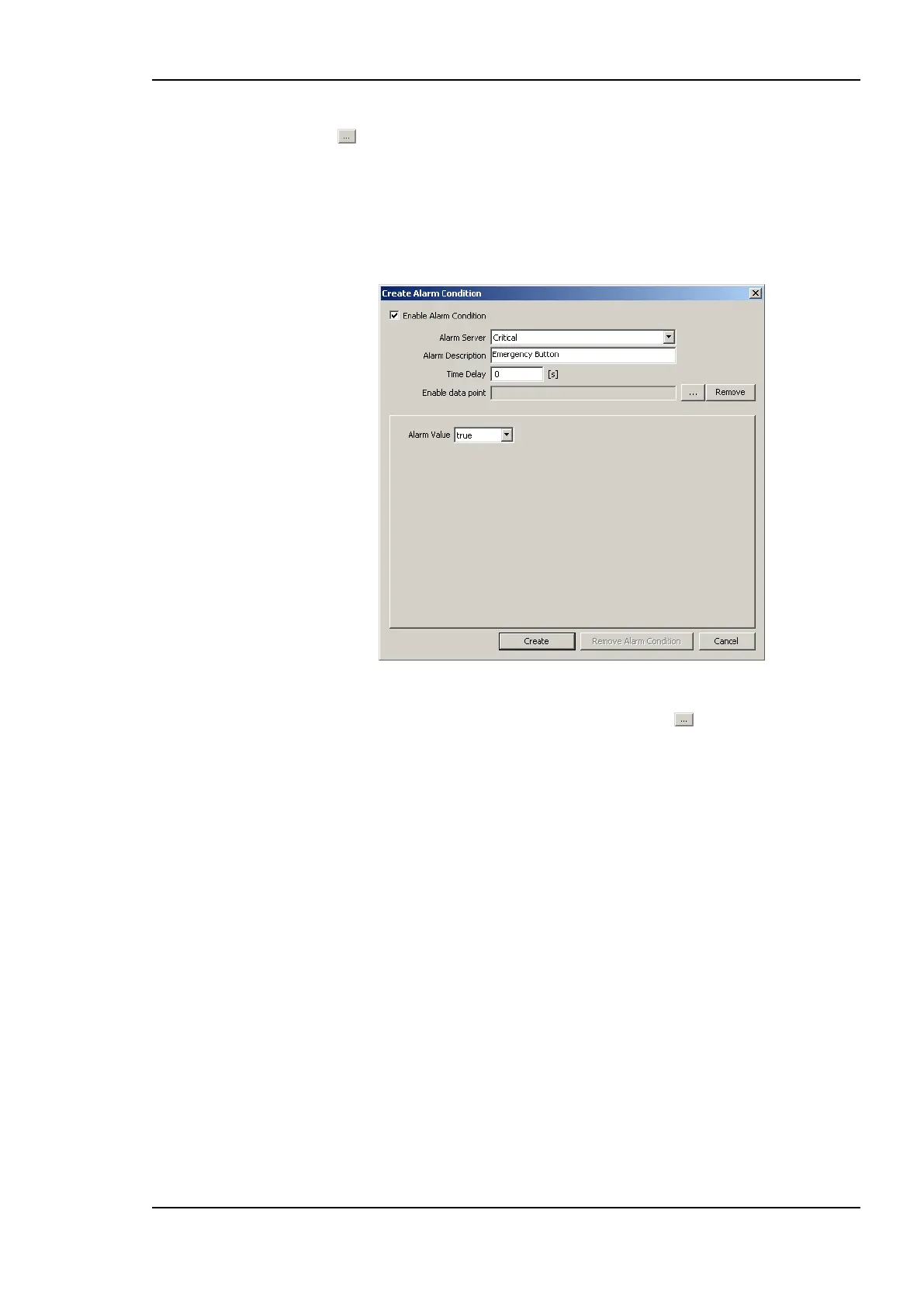
5. For a binary data point, the dialog as shown in Figure 145 appears. Select the Alarm
Server. Optionally, enter an Alarm Description. If left empty, the description of the
data point is used. Enter a Time Delay, after which the condition is evaluated. Select
the Alarm Value which triggers the alarm.
Figure 145: Alarm Condition for a Binary Data Point.
6. For enable, a data point can be attached by clicking the button. This data point is
used by the device to determine the actual values at run-time.
7. For a multi-state data point, the dialog as shown in Figure 146 appears. Select the
Alarm Server. Optionally, enter an Alarm Description. If left empty, the description
of the data point is used. Enter a Time Delay, after which the condition is evaluated.
Select the Alarm States, which triggers the alarm, by clicking the arrow buttons.