L-INX User Manual 246 LOYTEC
Version 4.0 LOYTEC electronics GmbH
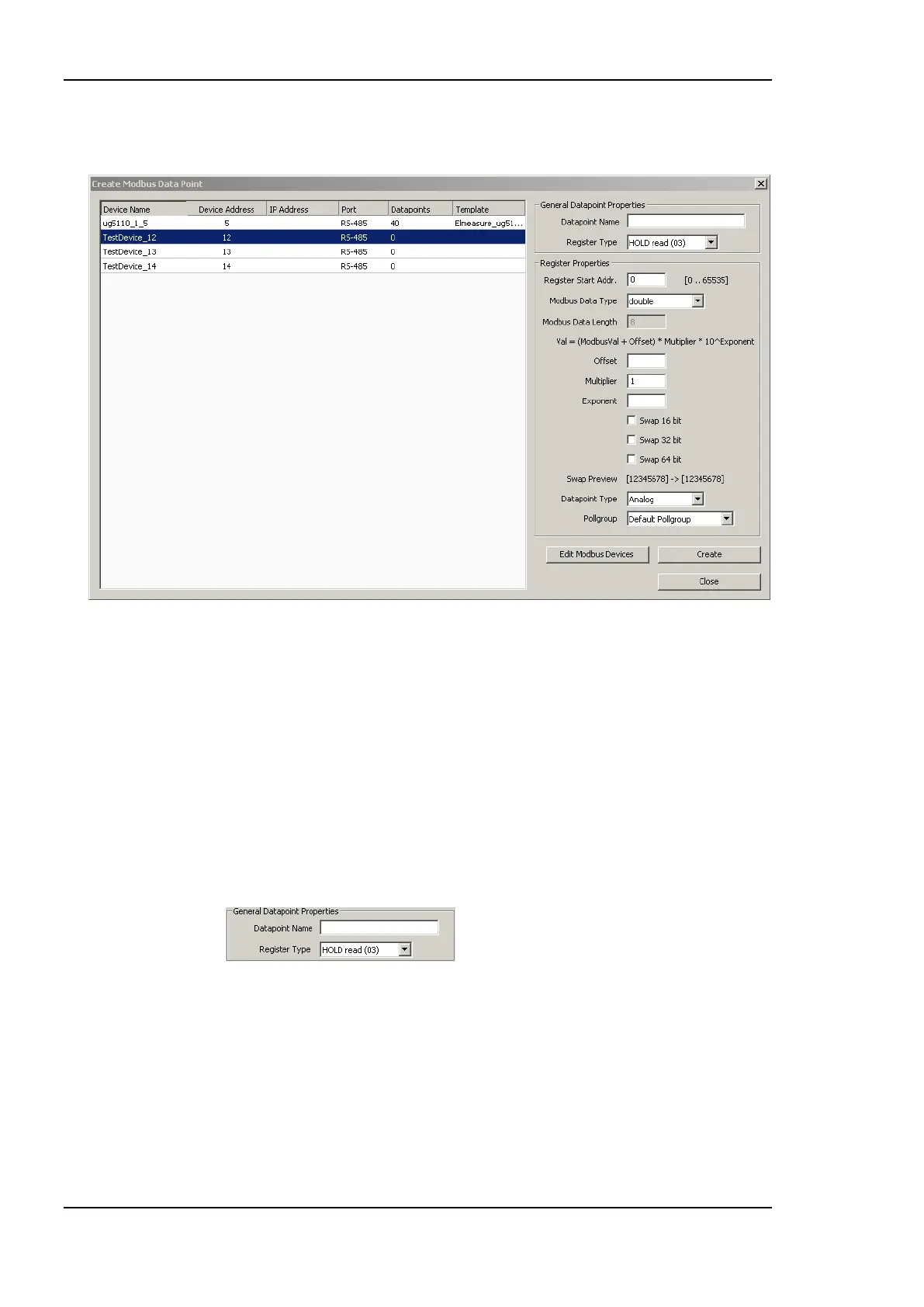
3. This opens the Create New Modbus Datapoint dialog showing only the devices
which are available on the appropriate port. This dialog is shown in Figure 192.
Figure 192 Create Modbus Datapoint dialog.
4. If the Modbus device which provides the data point is not in the list, it has to be
created. In this case open the Modbus Management dialog by clicking the Edit Modbus
Devices button.
5. Create the device in the Modbus Management dialog and close the dialog.
6. Select the device which provides the Modbus data point.
7. Enter the General Data Point Properties. These are the data point name, which is
automatically created when not specified, and the Register Type. The register type of
the data point is provided in the Modbus device documentation. The drop down menu
shows the Modbus register type, the direction (read and write) and the function code.
The data point properties are entered in the presented section of the dialog.
8. Enter the properties of the data point. The register address is specified by the
manufacturer. Select the Modbus Data Type. This type specifies how the
manufacturer stores data in the Modbus device. The Modbus Data Length is
automatically updated according to the data type. Offset, Multiplier and Exponent can
be used for mapping purposes. The Value of the data point is calculated as follows:
Value = (ModbusValue + Offset) ∙ Multiplier ∙ 10
Exponent
.
Modbus does not specify any byte orders of the data stored in devices. For some
devices it may be necessary to change the byte order. This is done by the check boxes