214683 314 Revision A
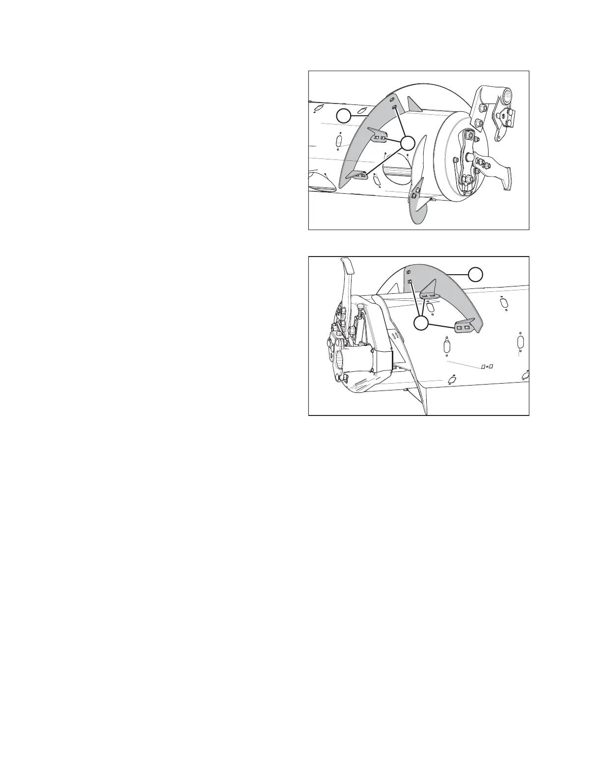
Figure 4.13: Medium Configuration (Right Side)
4. Install bolt-on flighting (A) on the right side of the auger
as shown, and secure with six carriage head bolts and
six nuts at location (B).
IMPORTANT:
Bolt heads must be installed on inside of auger to
prevent damage to internal components.
5. Torque all nuts and bolts to 47 Nm (35 lbf·ft) to eliminate
deflection on flighting, then torque them to 58–64 Nm
(43–47 lbf·ft).
Figure 4.14: Medium Configuration (Left Side)
6. Repeat Step 2, page 313 and Step 3, page 313 at the
left side of auger.
7. Install bolt-on flighting (A) on the left side as shown, and
secure with six carriage head bolts and six nuts at
location (B).
IMPORTANT:
Bolt heads must be installed on inside of auger to
prevent damage to internal components.
8. Torque all nuts and bolts (B) to 47 Nm (35 lbf·ft) to
eliminate deflection on flighting, then torque them to
58–64 Nm (43–47 lbf·ft).
9. Remove extra auger fingers. A total of 22 fingers are
recommended for this configuration. Refer to Removing
Feed Auger Fingers, page 429.
HEADER ATTACHMENT/DETACHMENT