214683 451 Revision A
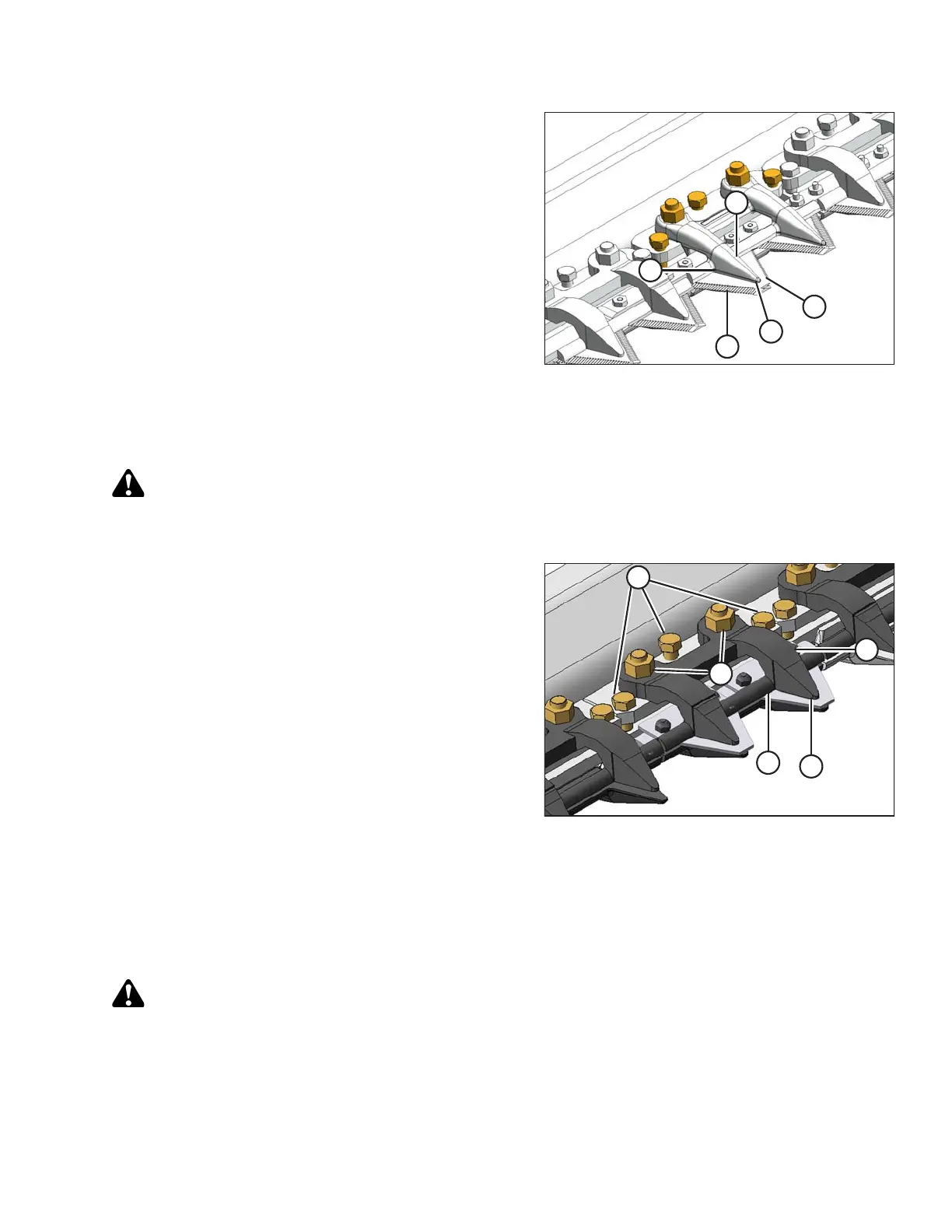
Figure 5.110: Double-Knife Center Stub Guard
Hold-Down
5. Double-knife center stub guard: Manually stroke
knife to locate sections under hold-down (B).
6. Measure clearance between knife sections (A) and (C)
with a feeler gauge. The clearance should be as
follows:
• At hold-down tip (D): 0.1–0.4 mm
(0.004–0.016 in.)
• At rear of hold-down (E): 0.1–1.0 mm
(0.004–0.040 in.)
7. If necessary, refer to Adjusting Hold-Downs with Stub
Guards, page 451.
Adjusting Hold-Downs with Stub Guards
WARNING
To avoid bodily injury or death from unexpected startup of machine, always stop engine and remove key
before making adjustments to machine.
Figure 5.111: Stub Guards
1. Shut down the engine, and remove the key from the
ignition.
2. Use a feeler gauge to measure the clearance between
the stub guard hold-down (A) and the knife section.
Ensure the clearance is between the following
measurements:
• At guide tip (B): 0.1–0.4 mm (0.004–0.016 in.)
• At rear of guide (C): 0.1–1.0 mm (0.004– 0.040 in.)
3. Adjust the clearance as follows:
a. Tighten nuts (D) until they are finger tight.
b. To lower the front of the hold-down and decrease
clearance, turn the three adjuster bolts (E)
clockwise; to raise the front of the hold-down and
increase clearance, turn the adjuster bolts (E)
counterclockwise.
c. Torque the nuts (D) to 72 Nm (53 lbf ∙ ft) after all the
adjustments are complete and the specified
clearances are achieved.
WARNING
Check to be sure all bystanders have cleared the area.
MAINTENANCE AND SERVICING