214683 375 Revision A
Figure 4.146: Float Module Underside
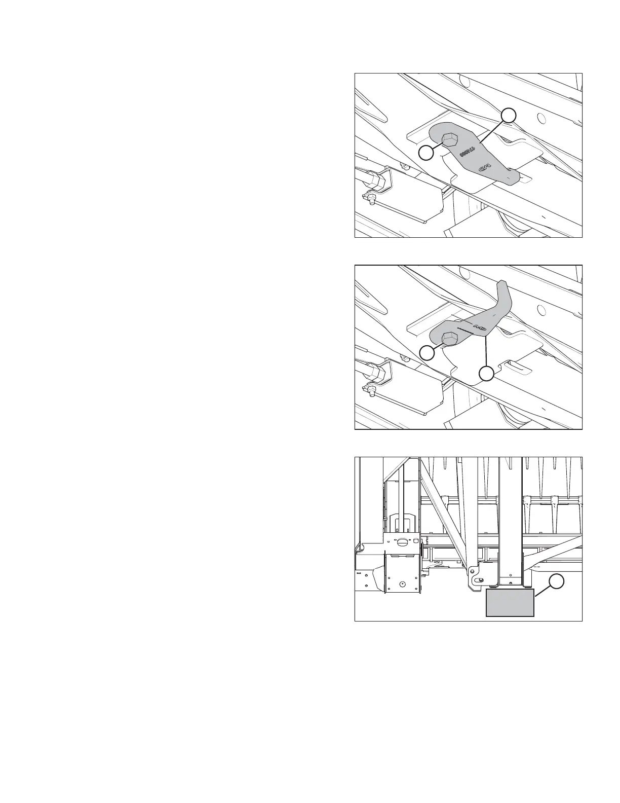
17. Loosen nut and bolt (A), and disengage hook (B) from
leg on both sides of float module.
Figure 4.147: Float Module Underside
18. Rotate hook (B) 90° for storage, and retighten bolt (A)
and nut.
Figure 4.148: Header Leg on Block
19. Place a 150 mm (6 in.) block (A) under the header leg.
This will assist with disconnecting the center-link.
20. Disengage combine lift cylinder locks, start engine, and
lower header until the header leg rests on the block or
stabilizer wheels are the ground.
HEADER ATTACHMENT/DETACHMENT