214683 498 Revision A
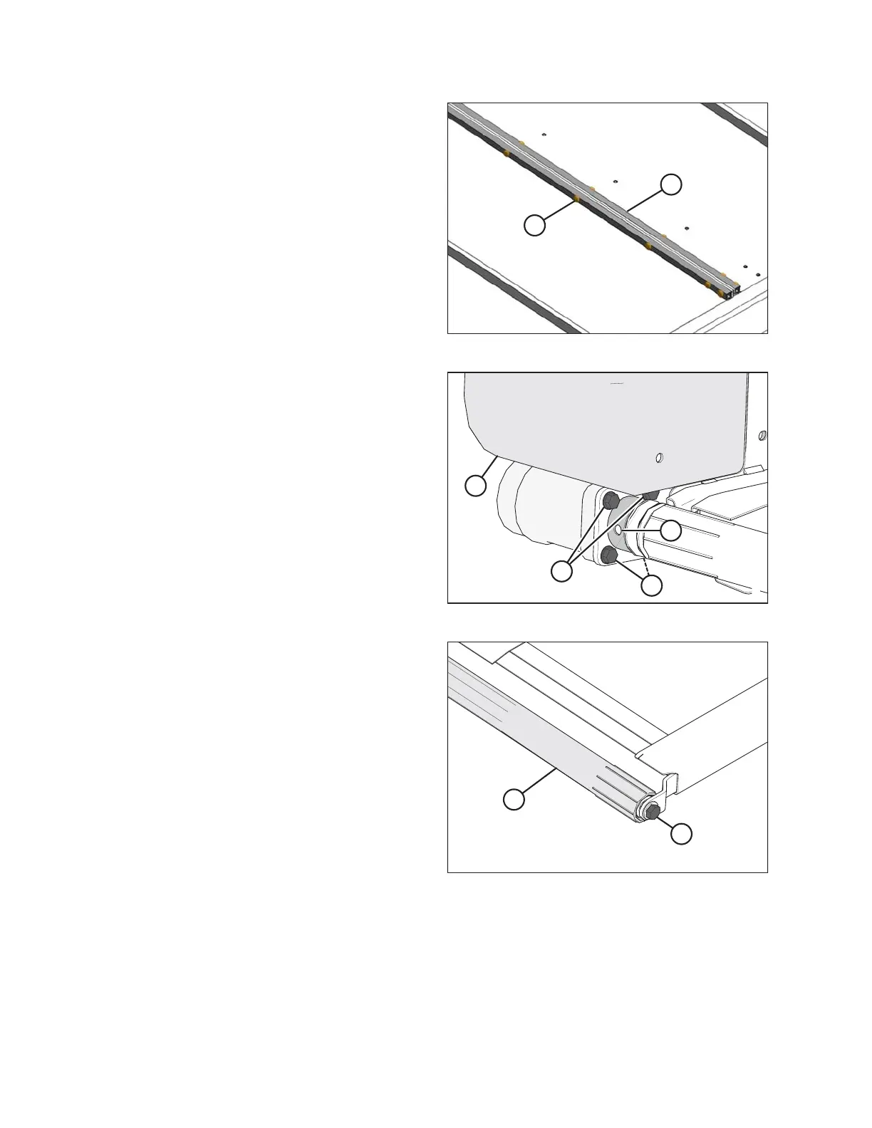
Figure 5.209: Draper Connector
4. Remove the tube connectors (B), screws (A), and nuts
from the draper joint to uncouple the draper.
5. Pull the draper off the drive roller.
Figure 5.210: Drive Roller
6. Align the setscrews with the hole (A) in the guard.
Remove the two setscrews holding the motor onto the
drive roller.
NOTE:
The setscrews are 1/4 turn apart.
7. Remove the four bolts (B) securing the motor to the
drive roller arm.
NOTE:
It may be necessary to remove the plastic shield (C) to
gain access to the top bolt.
Figure 5.211: Drive Roller
8. Remove the bolt (A) securing the opposite end of the
drive roller (B) to the support arm.
9. Remove the drive roller (B).
MAINTENANCE AND SERVICING